
Subscribe to Our Youtube Channel
Related Manuals for Harmonic Drive MMA Series


Summary of Contents for Harmonic Drive MMA Series
- Page 1 Flat Hollow Shaft AC Servo Motors compatible with Mitsubishi Electric MELSERVO-J4 series M M A s e r i e s m a n u a l ISO14001 ISO9001...
- Page 2 Introduction Introduction Thank you for purchasing our MMA series AC servo motor. Incorrect handling or improper use of this product may result in unexpected accidents or a shorter product life. Read this manual carefully and use the product correctly so that the product can be used safely for many years.
-
Page 3: Safety Guide
SAFETY GUIDE SAFETY GUIDE To use this product safely and correctly, be sure to read the SAFETY GUIDE and other parts of this document carefully and fully understand the information provided herein before using the product. NOTATION Important safety information you must note is provided herein. Be sure to observe these instructions. Indicates a potentially hazardous situation, which, if not avoided, could result in death or serious personal injury. -
Page 4: Safety Note
SAFETY GUIDE SAFETY NOTE ITEMS YOU SHOULD NOTE WHEN USING THE MOTOR CAUTIONS RELATED TO THE DESIGN Always use the motor under the specified conditions: The motor is designed to be used indoors. Observe the following conditions: ・ Ambient temperature: 0 to 40 ℃ CAUTION ・... - Page 5 SAFETY GUIDE ITEMS YOU SHOULD NOTE WHEN USING THE SERVO AMPLIFIER Read the related manuals to ensure safe operation. For details on the related manuals, refer to the [Related manual] (P6). Be sure to read the “MELSERVO-J4 SERIES AC SERVO SAFETY GUIDE”, which comes together with the servo amplifier, before using this product.
-
Page 6: Table Of Contents
Motor cable specifications ................. 1-19 Encoder cable specifications ................1-20 Chapter 2 Selection guidelines 2-1 MMA series selection ................... 2-1 Allowable load inertia moment ................2-1 2-2 Verifying and examining load weights ............2-2 2-3 Examining the operating status ..............2-3 Examining motor rotational speed ............... -
Page 7: Contents
Contents Chapter 3 Installing the motor 3-1 Receiving inspection ..................3-1 Inspection procedure ................... 3-1 3-2 Notices on handling ..................3-2 Installation and transmission torque ..............3-2 Precautions on installation ................... 3-3 Use of positioning pins ..................3-4 Motor material ..................... 3-4 3-3 Location and installation ................ -
Page 8: Related Manual
MMA series are provided. SPECIFICATIONS your servo amplifier. Conformance to overseas standards The MMA series motors are compliant with the following overseas standards. UL standards UL1004-1, UL1004-6 (File No. E243316) CSA standards C22.2 No.100... - Page 9 Conformance to overseas standards The values displayed on the name plate for each model are shown below. Model MMAB09 Item (1) Output at point A (2) Voltage at point A (3) Allowable continuous current (4) Speed at point A r/min 3000 (5) Frequency at point A (6) Allowable ambient temperature...
- Page 10 Conformance to overseas standards...
- Page 11 Chapter 1 Outlines This chapter explains the features, functions and specifications of the motor. 1-1 Outlines ·············································································· 1-1 1-2 Combinations with servo amplifier and extension cables ················ 1-2 1-3 Model ················································································· 1-4 1-4 Specifications······································································· 1-5 1-5 Holding brake······································································· 1-7 1-6 External dimensions ······························································ 1-8 1-7 Mechanical accuracy ···························································...
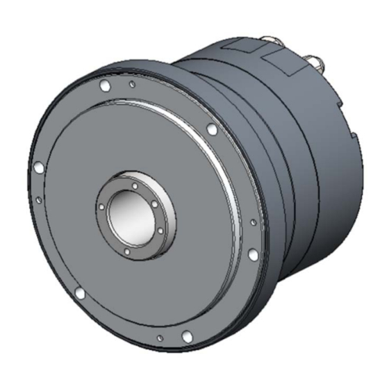
- Page 12 1-1 Outlines Outlines All MMA series AC servo motor models feature a hollow bore structure and compact design and they can be controlled with the SSCNETIII/H when combined with the Mitsubishi Electric AC servo amplifier MELSERVO-J4 series. Wires, pipes, ball screws, or laser beams go through the hollow bore depending on the mechanism design required for your applications.
-
Page 13: Combinations With Servo Amplifier And Extension Cables
1-2 Combinations with servo amplifier and extension cables Combinations with servo amplifier and extension cables The combinations of MMA motors, MR-J4-_B-S033 servo amplifiers, and extension cables are as follows: MMAB09 MMAB12 MMAB15 MMAA21A MR-J4- MR-J4- MR-J4- MR-J4- SSCNETIII/H type 60B-S033 100B-S033 200B-S033 500B-S033... - Page 14 1-2 Combinations with servo amplifier and extension cables Default Abbreviation Setting Name and function value (Note) range (units) PA17 *MSR Servo motor series setting 0000h 0000h When driving MMA motor, select the motor type with [Pr.PA17] and [Pr.PA18]. FFFFh Set at the same time as [Pr.PA18]. For the setting values, refer to the following table.
-
Page 15: Model
1-3 Model Model The model names for the MMA series motors and how to read the symbols are explained below. Model example: S17b (10) (11) (1) Model: MMA series AC servo motor (2) Motor version symbol Model No. 21A Model Nos. 09, 12, 15 (3) Model Nos.: 09, 12, 15, 21A... -
Page 16: Specifications
1-4 Specifications Specifications The specifications of the MMA series motors are shown below. Model MMAB09 MMAB12 MMAB15 MMAA21A Item MR-J4-60B- MR-J4-100B- MR-J4-200B- MR-J4-500B- Compatible servo amplifier S033 S033 S033 S033 Input power supply Rated output 1320 N・m Maximum momentary torque 0.31... - Page 17 1-4 Specifications Operating temperature: 0 to 40 ℃/Storage temperature: -20 to 60 ℃ Service/storage humidity: 20 to 80 % RH (no condensation) Resistance to vibration: 25 m/s (frequency: 10 to 400 Hz) 2 *5 Environmental conditions Resistance to impact: 300 m/s No dust, metal powder, corrosive gas, inflammable gas, or oil mist.
-
Page 18: Holding Brake
1-5 Holding brake Holding brake The brakes equipped on MMA series motors are used to hold the motor shaft in place when the power is cut off. With some models (MMAB09, 12), the motor's built-in circuit controls the voltage supplied to the brake in order to reduce the power consumption while the brake is actuated. -
Page 19: External Dimensions
1-6 External dimensions External dimensions The external dimensions of the MMA series motors are shown below. MMAB09 (with/without brake) Unit [mm] (third angle projection) Appe... - Page 20 1-6 External dimensions MMAB12 (with/without brake) Unit [mm] (third angle projection) Appe...
- Page 21 1-6 External dimensions MMAB15 (with/without brake) Unit [mm] (third angle projection) Appe 1-10...
- Page 22 1-6 External dimensions MMAA21A (with/without brake) Unit [mm] (third angle projection) Appe 1-11...
-
Page 23: Mechanical Accuracy
1-7 Mechanical accuracy Mechanical accuracy The mechanical accuracies of the output shaft and mounting flange for MMA series motors are shown below: Unit [mm] Accuracy items MMAB09 MMAB12 MMAB15 MMAA21A 1. Output shaft surface runout 0.020 0.020 0.040 0.040 2. Deflection of output shaft 0.020... -
Page 24: Detector Specifications (Absolute Encoder)
1-8 Detector specifications (Absolute encoder) Detector specifications (Absolute encoder) Absolute encoders installed in the MMA series are multi-turn absolute encoders. The encoder consists of a single-turn detector for detecting the motor shaft position, and a multi-turn detector for detecting the number of revolutions. -
Page 25: Rotation Direction
1-9 Rotation direction Rotation direction With the factory settings, the rotation direction is defined as counter-clockwise (CCW) as viewed from the output shaft when a pulse train is applied from the MELSERVO-J4 servo amplifier in the direction of rising position addresses. This rotation direction can be switched with the MELSERVO-J4 servo amplifier "Basic setting parameters (‘Pr.PA_ _’)"... -
Page 26: Shock Resistance
1-10 Shock resistance 1-10 Shock resistance The shock resistance of the motor is as follows, and this value is the same in up/down, left/right and front/rear directions: Shock acceleration: 300 m/s In our shock resistance test, the motor is tested three times in each direction. Motor operation is not guaranteed in applications where impacts exceeding the above value are constantly applied. -
Page 27: Resistance To Vibration
1-11 Resistance to vibration 1-11 Resistance to vibration The resistance to vibration of the motor is as follows, and this value is the same in up/down, left/right and front/rear directions: Vibration acceleration: 25 m/s (frequency: 10 to 400 Hz) In our test, the motor is tested for 2 hours in each direction at a vibration frequency sweep period of 10 minutes. -
Page 28: Operable Range
1-12 Operable range 1-12 Operable range The graphs below indicate the operable ranges of MMA series motors when combined with a MELSERVO-J4 servo amplifier. For details, refer to [2-1 MMA series selection]. 1. Continuous motion range This indicates a range in which the motor can be operated continuously as shown by the relationship between the torque and rotational speed. - Page 29 1-12 Operable range ■MMAB12 / MR-J4-100B-S033 Aluminum radiation plate: 400×400×20 [mm] アルミ放熱板:400×400×20 mm Motion range during 加減速運転領域 acceleration and deceleration Continuous 連続使用領域 motion range 1000 2000 3000 4000 5000 回転速度 [r/min] Rotation speed [r/min] ■MMAB15 / MR-J4-200B-S033 Aluminum radiation plate: 500×500×25 [mm] アルミ放熱板:500×500×25 mm Motion range during 加減速運転領域...
-
Page 30: Cable Specifications
1-13 Cable specifications 1-13 Cable specifications The following tables show the specifications of the motor and encoder cables for the MMA series motors. Motor cable specifications Model Nos. 09, 12, 15 Name Pin No. Color Without brake With brake... -
Page 31: Encoder Cable Specifications
1-13 Cable specifications Encoder cable specifications Model Nos. 09, 12, 15 Pin number Color Signal name Remarks Yellow Serial signal differential output (+) Blue Serial signal differential output (-) Orange Battery + No connection - No connection - No connection -... - Page 32 1-13 Cable specifications Appe 1-21...
-
Page 33: Chapter 2 Selection Guidelines
Chapter 2 Selection guidelines This chapter explains how to select a proper MMA series motor. 2-1 MMA series selection ····························································· 2-1 2-2 Verifying and examining load weights ········································ 2-2 2-3 Examining the operating status ················································ 2-3... -
Page 34: Mma Series Selection
Allowable load inertia moment To maximize the performance of the MMA series, make a tentative selection of a motor so that the rotational speed and load inertia moment ratio are equal to or lower than the allowable values shown in the table below. -
Page 35: Verifying And Examining Load Weights
Verifying and examining load weights For MMA series motors, ensure that the load applied to the center of rotation and the end of the output shaft does not exceed the permissible load in the table below. Values shown in the table are permissible loads when applied individually. -
Page 36: Examining The Operating Status
[mm] Linear travel speed [mm/min] Check that this motor rotational speed is less than the max. rotational speed of the MMA series motor. Calculating and examining load inertia moment Calculate the inertia moment of the load driven by an MMA series motor. -
Page 37: Load Torque Calculation
2-3 Examining the operating status Load torque calculation Calculate the load torque as follows: Rotary motion The rotary torque for rotating mass W on the ring of Mass: W radius r from the center of rotation is shown in the figure to the right. -
Page 38: Acceleration Time And Deceleration Time
2-3 Examining the operating status Acceleration time and deceleration time Calculate the acceleration and deceleration times for the motor tentatively selected using the following formula. × π × × × Acceleration time: − × π × × × Deceleration time: Rotational speed ×... -
Page 39: Evaluating Effective Torque And Average Rotational Speed
2-3 Examining the operating status Evaluating effective torque and average rotational speed One way to check if the heat generated from the motor during operation would present a problem is to determine if the point of operation, determined by the effective torque and average rotational speed, is inside the continuous motion range explained in [1-12 Operable range]. - Page 40 2-3 Examining the operating status (5) The * mark in the figure on the right shows the points of operation determined by the effective torque and average rotational speed calculated above, plotted on the graph of operable range of MMAB09, exceeding the continuous motion range. The conclusion is that this motor cannot be operated continuously under these conditions.
-
Page 41: Chapter 3 Installing The Motor
Chapter 3 Installing the motor This chapter explains how to install the motor. 3-1 Receiving inspection ······························································ 3-1 3-2 Notices on handling ······························································· 3-2 3-3 Location and installation ························································· 3-5... -
Page 42: Receiving Inspection
Check if the motor is what you ordered. The nameplate is found on the end face or the side of the MMA series motor. Check the TYPE field on the nameplate to confirm that it is the model you have ordered. If any item is different from what you ordered, immediately contact the dealer. -
Page 43: Notices On Handling
Practice caution and observe the following notices when handling MMA series motors. Do not apply any excessive force or impact, especially to the motor's output shaft. Do not place MMA series motors on a table, shelf, etc., where the motor could easily fall. CAUTION Do not connect the motor terminals directly to the power supply. -
Page 44: Precautions On Installation
When designing the assembly, note that application of any abnormal or excessive force that causes deformation of the installation surface may result in performance drop. To deliver optimal performance of the MMA series motors, pay attention to the following points: Warping and deformation on the mounting surface ... -
Page 45: Use Of Positioning Pins
3-2 Notices on handling Use of positioning pins The MMA series motors have positioning pin holes in the output shaft. Use these pin holes as necessary. For details, refer to [1-6 External dimensions] (P1-8) or the illustrated specifications. Positioning pin*... -
Page 46: Location And Installation
3-3 Location and installation Location and installation Environment of location The environmental conditions of the installation location for MMA series motors are as follows. Always observe these conditions to determine an appropriate installation location. ◆ Operating temperature: 0 to 40 ℃... -
Page 47: Installation
3-3 Location and installation Installation When installing an MMA series motor, ensure that it is installed accurately and do not tap with a hammer, etc. The motor houses an encoder. Excessive impact may damage the encoder. Installation procedure Align the axis of rotation of the motor and the Output load mechanism precisely. - Page 48 3-3 Location and installation Appe...
-
Page 49: Options
Chapter 4 Options This chapter provides information on the options. 4-1 Options ·············································································· 4-1... -
Page 50: Cable Taken Out From Side Face (Option Code: Y)
4-1 Options Options Cable taken out from side face (option code: Y) The cables (motor and encoder wires) are taken out from the side face of the motor. Use this option if the motor is housed in a system and there is not enough space at the rear of the housing. -
Page 51: Extension Cables
These extension cables are used to connect MMA series motors and MELSERVO-J4 servo amplifiers. Two types of extension cables are available for motor (including brake wire) and encoder. You must use an extension cable to connect your MMA series motor and MELSERVO-J4 servo amplifier. - Page 52 4-1 Options Motor model No. 21A EWD-MB ** -D09-TMC-M2 ** in the model code indicates the cable length (02 = 2m, 05 = 5m, 10 = 10m). [Moor side] [Servo amplifier side] Cable length PE: green/yellow U: red V: white W: black Solder processing Brake: blue...
-
Page 53: Appendix
Chapter 5 Appendix Unit conversion ································································· 5-1 Calculating inertia moment ·················································· 5-3... -
Page 54: Unit Conversion
Unit conversion 13-1 Unit conversion This manual employs the SI system for units. Conversion factors between the SI system and other systems are as follows: (1) Length SI system Unit Factor 0.3048 0.0254 Unit Factor 3.281 39.37 SI system (2) Linear speed SI system Unit m/min... - Page 55 Unit conversion (8) Angular acceleration SI system rad/s Unit deg/s deg/min Factor 0.01755 2.93 x 10 Unit deg/s deg/min Factor 57.3 3.44 x 10 SI system rad/s (9) Torque SI system N・m Unit kgf・m lb・ft lb・in oz・in Factor 9.81 1.356 0.1130 7.06 x 10 kgf・m lb・ft...
-
Page 56: Calculating Inertia Moment
Calculating inertia moment 13-2 Calculating inertia moment Formulas of mass and inertia moment (1) The center of rotation matches the centroidal line The following table includes formulas to calculate mass and inertia moment. m: Mass [kg], Ix, Iy, Iz: inertia moments which rotate around x-, y-, z-axes respectively [kg・m G: Distance from the end face to the center of gravity [m] ρ: Specific gravity [ kg / m... - Page 57 Calculating inertia moment Object form Mass, inertia, gravity center Object form Mass, inertia, gravity center Rhombus pillar Hexagonal pillar ×10 ρ ×10 ρ B√3 Ix = Isosceles triangle Right triangle pillar ×10 ×10...
-
Page 58: Inertia Moment Of Cylinder
Calculating inertia moment Inertia moment of cylinder The inertia moment of a cylinder can Inertia moment [kg・m Length [mm] be obtained from the graphs to the 1000 Inertia moment (specific gravity: 2.7) right. 1000 Radius Length Apply the top graph to aluminum Appe materials (specific gravity: 2.7) and bottom graph to steel materials... - Page 59 Load weights ............2-2 A Absolute encoder ..........1-13 Mechanical accuracy ......... 1-12 Acceleration time ..........2-5 MMA series selection........... 2-1 Allowable load inertia moment ......2-1 Model ..............1-4 Average rotational speed ........2-6 Motor cable specifications ......... 1-19 Motor rotational speed .........
- Page 61 (2) disassembling, modification or repair by others than Harmonic Drive Systems, Inc. (3) imperfection caused by a non-applicable product. (4) disaster or others that does not belong to the responsibility of Harmonic Drive Systems, Inc. Our liability shall be limited exclusively to repairing or replacing the product only found by Harmonic Drive Systems, Inc.
- Page 62 Harmonic Drive L.L.C/247 Lynnfield Street, Peabody, MA, 01960, U.S.A. TEL+1- 978-532-1800 FAX+1- 978-532-9406 ® "HarmonicDrive " is a registered trademark of Harmonic Drive Systems, Inc. No.1907-0R-TMMA-E The academic or general nomenclature of our products "HarmonicDrive " is "strain wave gearing."...
Need help?
Do you have a question about the MMA Series and is the answer not in the manual?
Questions and answers