Table of Contents
Advertisement
Quick Links
Advertisement
Table of Contents

Related Manuals for Harmonic Drive KDU Series


Summary of Contents for Harmonic Drive KDU Series
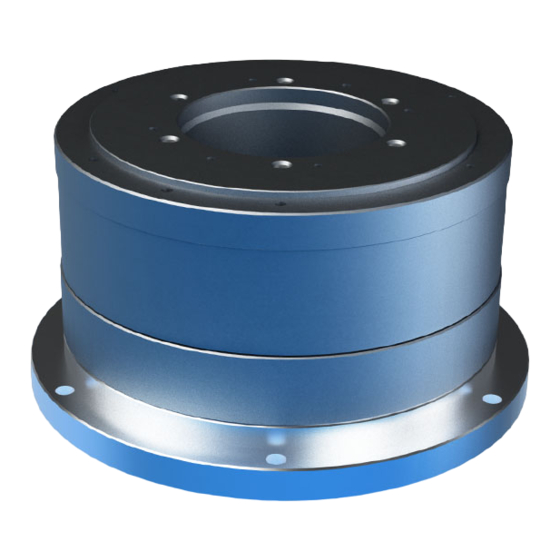
- Page 1 Direct Drive Motor K D U S e r i e s M a n u a l ISO14001 ISO9001...
- Page 2 Introduction Introduction Thank you very much for purchasing our KDU Series Direct Drive Motor. Wrong handling or use of this product may result in unexpected accidents or shorter life of the product. Read this manual carefully and use the product correctly so that the product can be used safely for many years.
-
Page 3: Safety Guide
SAFETY GUIDE SAFETY GUIDE To use this product safely and correctly, be sure to read the SAFETY GUIDE and other parts of this document carefully and fully understand the information provided herein before using the driver. Notation Important safety information you must note is provided herein. Be sure to observe these instructions. Indicates a potentially hazardous situation, which, if not avoided, could result in death or serious personal injury. -
Page 4: Safety Note
SAFETY GUIDE SAFETY NOTE ITEMS YOU SHOULD NOTE WHEN USING THE MOTOR NOTICES ON DESIGN Always use them under the followings conditions: The motor is designed to be used indoors. Observe the following conditions: ・ Ambient temperature: 10 to 30℃ ・... - Page 5 SAFETY GUIDE ITEMS YOU SHOULD NOTE WHEN USING THE DRIVER NOTICES ON DESIGN Always use them under followings conditions: The driver generates heat. Take extra caution for radiation and use it under the following conditions. CAUTION ・ Mount in a vertical position keeping sufficient distance to other devices to let heat generated by the driver radiate freely.
- Page 6 SAFETY GUIDE Do not make a voltage resistance test. ・ Do not perform a megger test or voltage resistance test. Failure to observe this caution may result in damage to the control circuit of the driver. CAUTION ・ Please consult our sales office, if you intent to make a voltage resistance test.
-
Page 7: Structure Of This Document
Structure of this document Structure of this document This chapter explains overviews of motor models, specifications, Chapter 1 Overviews external dimensions, etc. Chapter 2 Installation This chapter explains how to install the motor. Chapter 3 Option This chapter explains options. This chapter explains unit conversion and method of calculating inertia Appendix moment. -
Page 8: Table Of Contents
Contents SAFETY GUIDE ....................1 Notation ........................1 LIMITATION OF APPLICATIONS................1 SAFETY NOTE ...................... 2 Structure of this document ..................5 Contents ....................6 Chapter 1 Overviews ....................1 Main features......................1 Model ....................2 Combination with driver ................3 Specifications .................... -
Page 9: Contents
Contents Environmental conditions of installation location ............. 3 Installation ......................5 Chapter 3 Extension cable..................... 1 Communication cable ................... 2 Standard combination ................... 3 Appendix Appendix-1 Unit conversion ................1 Appendix-2 Inertia moment calculation ............3 1. Formula of mass and inertia moment ............... 3 2.Inertia moment of cylinder ................. - Page 10 Contents Memo...
-
Page 11: Overviews
Chapter 1 Overviews Overviews of motor models, specifications, external dimensions, etc., are explained in this chapter. Overviews ··········································································· 1 Model ················································································ 2 Combination with driver ························································· 3 Specifications ······································································ 4 External dimensions ······························································ 6 External drawing ·································································· 8 Absolute positional accuracy ··················································· 9 Repeatability ·····································································... -
Page 12: Main Features
KDU Series Direct Drive Motor offers high precision positioning with super high resolution. The KDU Series dedicated HA-770 driver is a servo drive units that can control position by command communication command and pulse command. The small, multi-functional drivers control the operations of KDU Series motors with great accuracy and precision. -
Page 13: Model
200: 200V AC Specification symbol No symbol : Standard specification product Model names for the KDU Series Direct Drive Motors and how to read the symbols are explained below. KDU-13S B-E 10-□ Model: KDU Series Direct Drive Motor Model No.: 13S, 13W... -
Page 14: Combination With Driver
200V KDU-13WB-D3-200 KDU-13WB-E10 Use the KDU Series motor combined with a driver as a set. The KDU Series motor's absolute positional accuracy of 10 seconds is based on correction data from the driver memory. If you use a motor CAUTION and driver combination that is not shown, the absolute positional accuracy cannot be guaranteed. -
Page 15: Specifications
1-4 Specifications Specifications Below is the specifications of the KDU Series motors. Model Item -13SB -13WB 15.0 Max. torque Note 2 kgfm Max. rotational speed r/min N m/A Torque constant kgfm/A 0.32 0.66 Input power supply AC100/AC200 EMF constant V/(r/min) 0.33... - Page 16 1-4 Specifications Notices for maintaining accuracy To maintain accuracy, observe the following notices when using the motor. Use the product in an appropriate environment. The environmental conditions for our accuracy measurement are a temperature of 23±0.3℃ and relative humidity of 50%. When using the motor in a device that requires high accuracy positioning control, please take into account the stiffness of the mechanism for temperature change of up to ±3 ˚C, the coefficient of expansion for each part, external vibration, etc.
-
Page 17: External Dimensions
1-5 External dimensions External dimensions The external dimensions of the KDU Series are shown below. KDU-13SB-E10 Encoder Interpolator Interpolator Unit: mm (third angle) Unit: mm (third angle projection) Motor connector Tap for fixing the rotating part 6-M5X8 Hole for fixing the stopper part ⌀... - Page 18 1-5 External dimensions Encoder Interpolator Unit: mm (third angle projection) 付...
-
Page 19: External Drawing
1-6 External drawing External drawing The mechanical accuracies of the output shaft and mounting flange are shown below for the KDU Series motor: unit: mm Accuracy items KDU-13 1. Output shaft surface runout 0.002 2. Deflection of output shaft 0.040 3. -
Page 20: Absolute Positional Accuracy
1-7 Absolute positional accuracy Absolute positional accuracy Max. positioning error Actual stop position 0° 360° Theoretical position "Absolute positional accuracy" The accuracy is measured with measurement comparing with a reference encoder. Rotating one revolution with the Z signal as the datum point, the difference between the actual measured value at each positioning point (the position actually moved to from the datum point) and the reference encoder is found, and the value of (maximum –... -
Page 21: Repeatability
1-8 Repeatability Repeatability Repeatability From any A0 point position, move a certain angle. Make this point the A1 point. Move the same distance in reverse as you moved from the A0 point. Measure the stop position P1 with the measuring instrument. From the P1 point, repeat the same operations as in 1 and measure the P2 point. -
Page 22: Moment Stiffness
The moment stiffness refers to the torsional stiffness when a moment capacity is applied to the output shaft of the KDU Series motor (shown in the figure to the right). For example, when a load is applied to the end of an arm attached on the output shaft of the KDU Series motor, the face of the output shaft tilts in proportion to the moment load. -
Page 23: Axial Load And Moment Load
1-10 Axial load and moment load 1-10 Axial load and moment load For the positional accuracy of the KDU Series motor, the accuracy is checked with an output shaft load of 16 kg or less for an axial load. Axial load: 16 kg or less If an axial load larger than 16 kg or a moment load is applied, this affects the positional accuracy. -
Page 24: Rotation Direction
Rotation direction Forward rotation direction of the motor is defined as counter-clockwise rotation as viewed from the output shaft when a Forward command is given to a KDU Series motor from a HA-770 driver. FWD rotation: counter-clockwise as viewed from the output shaft 付... -
Page 25: Resistance To Vibration And Impact
While transporting or mounting the motor, do not subject the motor to any vibration or impact. In order to use KDU Series motor with high accuracy, use it in an environment with no impact or vibration. -
Page 26: Allowable Load Inertia Moment
1-13 Allowable load inertia moment 1-13 Allowable load inertia moment The graph below shows the relationship between the KDU-13SB and KDU-13WB load inertia moment and the 90˚ positioning time. To select the load conditions, refer to the load inertia moment in the graph below. -
Page 27: Operable Range
1-14 Operable range 1-14 Operable range The graph on the next page indicates the operable range when a KDU Series motor (combined with a HA-770 driver) is selected. Operable range For the maximum rotational speed and the maximum torque, the range in which the product can be For position indexing operations for normal acceleration and operated in the instant are shown. -
Page 28: Cable Specifications
1-15 Cable specifications 1-15 Cable specifications The following tables show specifications of the motor and encoder cables of the KDU Series motors. Motor drive cable Pin layout Pin No. Color Signal name Remarks Motor phase-U U Motor phase-V White V... - Page 29 Chapter 2 Installation This chapter explains how to install the motor. Receiving inspection ····························································· 1 Notices on handling ······························································ 2 Installation location and installation ··········································· 3...
-
Page 30: Receiving Inspection
Refer to the Chapter 1 [1-2 Model] (page 1) in this manual for details of the model codes. 3. The serial number of the KDU Series motor that should be combined with the HA-770 is written on the HA-770 driver nameplate. -
Page 31: Notices On Handling
(1) Do not apply any excessive force or impact, especially to the output shaft of the KDU Series motor. (2) Do not put the KDU Series motor on a table, shelf, etc., where the motor could easily fall. (3) The allowable storage temperature is -10 to +60 ゚ C. Do not... -
Page 32: Installation Location And Installation
Installation Installation location and installation Environmental conditions of installation location The environmental conditions of the installation location for KDU Series motor must be as follows. Determine an appropriate installation location by observing these conditions without fail. Operating temperature: 10 to 30℃... - Page 33 2-3 Installation location and installation Installation Notices for maintaining accuracy To maintain accuracy, observe the following notices when using the motor. Use the product in an appropriate environment. The environmental conditions for our accuracy measurement are a temperature of 23±0.3℃...
-
Page 34: Installation
The KDU Series motor drives mechanical load system at high accuracy. When installing the motor, pay attention to precision and do not tap the output section of KDU Series motor with a hammer, etc. Excessive impact may damage the encoder and make it impossible to guarantee the positional accuracy. - Page 35 Chapter 3 Option The following explains the options. Extension cable ···································································· 1 Communication cable ···························································· 2 Standard combination ···························································· 3...
-
Page 36: Extension Cable
Option Extension cable This extension cable connects the KDU Series direct drive motor and the driver. There are two types of relay cable: for motors and incremental encoder. Extension cable model (** indicates the cable length of 3m or 5m.) ... -
Page 37: Communication Cable
3- 2 Communication cable Option Communication cable The RS-422/RS-485 cable is used to communicate with the HA-770 driver. Cable model: HDM-RS422-HA770 Connector cable Signal cable Pin No. Color RS422 RS485 Red/White NTXD NTRX Green Green/White NRXD Yellow Yellow/White Black Shield 付... -
Page 38: Standard Combination
3- 3 Standard combination Option Standard combination The following are the standard combinations of , servo driver, and KDU Series Direct Drive Motor cable. extension For incremental encoders Entire length of Driver Extension cable System model Max. Motor model cable... -
Page 39: Appendix
Appendix ·························································· Appendix-1 Unit conversion 1 ············································ Appendix-2 Inertia moment calculation 3... -
Page 40: Unit Conversion
Unit conversion Appendix 13-1 Unit conversion Appendix This manual employs SI system for units. Conversion factors between the SI system and other systems are as follows: (1) Length Unit system Factor 0.3048 0.0254 Unit Factor 3.281 39.37 SI system (2) Linear speed Unit m/min ft./min... - Page 41 Unit conversion (8) Angular acceleration rad/s Unit deg/s deg/min system Factor 0.01755 2.93x10 Unit deg/s deg/min Factor 57.3 3.44x10 SI system rad/s (9) Torque N・m Unit kgf・m lb・ft lb・in oz・in system Factor 9.81 1.356 0.1130 7.06x10 kgf・m lb・ft lb・in oz・in Unit Factor 0.102...
-
Page 42: Appendix-2 Inertia Moment Calculation
Inertia moment calculation Appendix Appendix 13-2 Inertia moment calculation 1. Formula of mass and inertia moment (1) Both centerlines of rotation and gravity are the same: The following table includes formulas to calculate mass and moment of inertia. m :mass (kg), Ix, Iy, Iz: inertia moments which rotates around x-, y-, z-axes respectively (kg・m G :distance from end face of gravity center (m) ρ... - Page 43 Inertia moment calculation Mass, inertia, gravity Mass, inertia, gravity Object form Object form center center Rhombus pillar Hexagonal pillar ρ ρ B√3 Ix = Isosceles triangle Right triangle pillar ABCρ...
- Page 44 Inertia moment calculation Appendix (3) Inertia moment of linearly moving objects The inertia moment, converted to FHA-C actuator axis, of a linear motion object driven by a screw, etc., is calculated using the formula below: π ...
-
Page 45: 2.Inertia Moment Of Cylinder
Inertia moment calculation 2.Inertia moment of cylinder The moment of inertia of a cylinder Moment of inertia (kgm Length (mm) may be obtained from the graphs to 1000 1000 Moment of inertia (Specific gravity 2.7) the right. 1000 Radi Lengt Apply the top graph to aluminum materials (specific gravity: 2.7) and bottom graph to steel materials... - Page 46 Index Absolute positional accuracy ........9 Model ..............2 Combination with driver .......... 3 Moment stiffness ........... 11 Extension cable ............1 Operable range ............ 17 External dimensions ..........6 Overviews ............... 1 External drawing ............. 8 Repeatability ............10 Inertia moment ............
- Page 47 (2) disassembling, modification or repair by others than Harmonic Drive Systems, Inc. (3) imperfection caused by the other than the KDU series actuator and the HA-720 servo driver. (4) disaster or others that does not belong to the responsibility of Harmonic Drive Systems, Inc.
- Page 48 42 Dunham Ridge, Beverly, Massachusetts 01915 U.S.A. L.L.C.: TEL: +1-978-532-1800 FAX: +1-978-532-9406 ® "HarmonicDrive " is a trademark of Harmonic Drive Systems, Inc. No. 2107-3R-TKDU2-E ® The academic or general nomenclature of our products "HarmonicDrive " is "strain wave gearing."...
Need help?
Do you have a question about the KDU Series and is the answer not in the manual?
Questions and answers