American Dynamics ADSDUHOC Installation Manual
Outdoor housing
Hide thumbs
Also See for ADSDUHOC:
- Datasheet (4 pages) ,
- Specifications (24 pages) ,
- Specifications (24 pages)
Table of Contents
Advertisement
SpeedDome
®
Outdoor Housing
Installation Guide-Continuation
ADSDUHOC
ADSDUHOS
ADSDUHOVRC
ADSDUHOVRS
Contents:
To the Installer....................................................... 3
About the Product.................................................. 3
Parts Supplied ....................................................... 3
Tools Required ...................................................... 3
Warnings and Cautions ......................................... 4
Preventing Condensation ...................................... 5
Parts List for Authorized Users ............................. 5
Connector Pin Assignments .................................. 6
Cable Requirements.............................................. 6
Troubleshooting..................................................... 9
Specifications ...................................................... 11
Declarations ........................................................ 12
© 2007 Sensormatic Electronics Corp.
SPEEDDOME ULTRA OUTDOOR HOUSING
INSTALLATION GUIDE - CONTINUATION
Ultra
To the Installer
This guide assumes that the outdoor mounting
structure to which the housing is attached is in
place and that data and power cables have been
pulled to the installation site. To install the outdoor
mounting structure, see documents shipped with
the structure.
About the Product
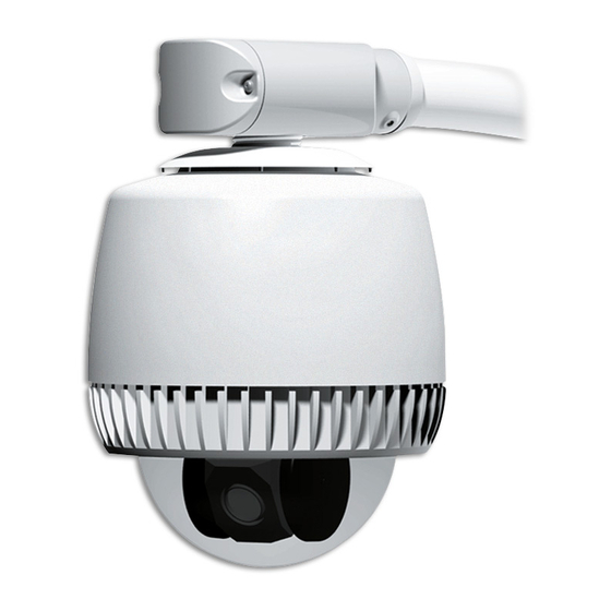
The outdoor housing has a sunshield cover and
bubble that protect the SpeedDome Ultra dome
camera. Tamperproof screws affix the bubble to
the housing.
The housing is temperature controlled and
weatherproof. A built-in thermostat and heater
prevent ice from forming on the outside of the
bubble.
The non-vandal resistant version has four alarm
inputs and one SPDT relay. Surge protection is
provided on all external lines, including video.
Parts Supplied
• Housing assembly 0101-0115-03
• Housing assembly, vandal-resistant
0101-0116-03
• Bubble assembly 0404-1402-01 (Clear) /
-02 (Smoked)
• Tamperproof drive 1400-0149-01
• Install kit 0352-0248-03
Purchase or Supply Separately
Male BNC connector
Tools Required
• 6.6mm (1/4in) fixed-handle nut driver for
Torx bit
• Wire cutters and strippers
• 2.5mm (0.1in) slotted screwdriver
3 of 12
8200-0492-02, REV. B
Advertisement
Table of Contents

Related Manuals for American Dynamics ADSDUHOC


Summary of Contents for American Dynamics ADSDUHOC
-
Page 1: Table Of Contents
SpeedDome Ultra ® Outdoor Housing Installation Guide–Continuation ADSDUHOC ADSDUHOS ADSDUHOVRC ADSDUHOVRS Contents: To the Installer... 3 About the Product... 3 Parts Supplied ... 3 Tools Required ... 3 Warnings and Cautions ... 4 Preventing Condensation ... 5 Parts List for Authorized Users ... 5 Connector Pin Assignments ... -
Page 2: Warnings And Cautions
Amps, meeting section 2.11 of IEC950, and a maximum of 250VA available. The power supply can be obtained through American Dynamics or through another source where the provider can furnish the required certification. This is required to assure electrical safety in the product. -
Page 3: Preventing Condensation
Preventing Condensation Damage, missing parts, or procedures that most often allow water to enter the housing are as follows (refer to figures opposite): Missing O-ring on cover, or missing sleeve or seal on end cap assembly Missing Teflon tape around any housing pipe threads RTV or similar sealant covering an air path Blower fans not turning... -
Page 4: Connector Pin Assignments
Connector Pin Assignments GREEN CONNECTOR (POWER) Color Description Black 24Vac White Common 24Vac BLACK CONNECTOR (DATA) Manchester Color* Designation — Not used. White/Orange Manchester (White) White/Yellow Manchester (Black) RS-422 / SensorNet Color* Designation Orange RS-422 Data In High (+) Green RS-422 Data In Low (–) Yellow RS-422 Data Out High (+) -
Page 5: Housing Termination And Video Configuration
Housing Termination and Video Configuration Both the outdoor housing and dome camera are shipped “terminated” for when they are installed at the end of a data cable. Should the cable continue to another dome, “unterminate” the housing using the following procedure. IMPORTANT! Leave the dome camera set to “terminated.”... - Page 6 3. On the circuit board is a mark (shown below). To reattach the board to the housing, match the mark to an identical mark on the base and snap the board in place. 4. Gently remove the dust cover. Note: Keep the cover and use it to protect contacts should the environmental PC board need to be removed from the housing.
-
Page 7: Troubleshooting
Troubleshooting This section covers what to do when: • Dome does not respond to commands • Fans do not turn • Picture is grainy or discolored • Poor video • Ice forms on bubble. CAUTION: Some steps in this section involve tightening wire connections. - Page 8 SensorNet Data Connections Color Designation — Not used. White/Orange SensorNet (unshielded) White/Yellow SensorNet (unshielded) 4. Check fans. Are they on? - YES: Continue. - NO: Go to “Fans Do Not Turn” procedure next. 5. Check video on monitor. Does the picture roll? - YES: Use the video controller or switcher to synchronize video vertical sync phases of all domes to the ac line.
-
Page 9: Specifications
Ice Forms On Bubble Follow steps until the problem is corrected. See page 5 to order parts. 1. Are blower/heater fans in the housing working? If not, see “Fans Do Not Turn” opposite. 2. Is the camera dome receiving power? Look for evidence such as a picture on the video monitor or dome movement. -
Page 10: Declarations
SPEEDDOME ULTRA OUTDOOR HOUSING INSTALLATION GUIDE - CONTINUATION Other Declarations Thank you for using American Dynamics products. We support our products through an extensive and worldwide network of dealers. The dealer, through whom you originally purchased this product, is your point of contact if you have a need for service or support.
Need help?
Do you have a question about the ADSDUHOC and is the answer not in the manual?
Questions and answers