
Related Manuals for AccuTemp XLR81B-00 Series

Summary of Contents for AccuTemp XLR81B-00 Series
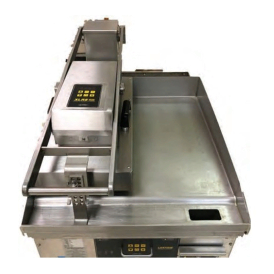
- Page 1 Serial Number: Model: XLR8 HEATED PLATEN INSTALL, SERVICE AND PARTS AccuTemp Products INC 11919 John Adams Drive, New Haven, IN 46774 www.accutemp.net MP5032-2104...
-
Page 2: Table Of Contents
TABLE OF CONTENTS DESCRIPTION PAGE INSTALLATION & OPERATION Table of Contents / Document History Safety Warnings General Info Installation Operation Planned Maintenance SERVICE Sequence of Operation Troubleshoot Guide Removal & Replacement of Parts PARTS Warranty DOCUMENT HISTORY Current Revision Date Prior Revision Date Revision... -
Page 3: Safety Warnings
1. WARNING SYMBOL DEFINITIONS SYMBOL DEFINITIONS Symbols are used to attract your attention to possible dangers. They are only e ective if the operator uses proper accident prevention measures. Some of the symbols are boxed text; while others maybe just picture icons. Please give this information the respect they deserve for safe operation. -
Page 4: General Info
AccuTemp product may be covered by one or more US Patents. See www.accutempip.net " AccuTemp Products, Inc. 8415 North Clinton Park • Fort Wayne, IN 46825 • 800-210-5907 • 260-493-0415 • Fax 260-493-0318 • accutemp.net " (COOKING HEIGHT) XLR8 HEATED PLATEN... -
Page 5: Installation
TOOLS REQUIRED: 3.4 LOCATION AND PLACEMENT Spirit Level The XLR8 electric equipment has been designed Phillips Screw Driver to be mounted on an AccuTemp AccuSteam Small Blade Straight Screw Driver griddle. Digital Clamp Ammeter Multimeter The operating temperature of the platen ranges Weighted Temperature Probe from 150°- 440°F (65.5°- 226°C). - Page 6 Any in-field modifications made without with the National Electric Code, NFPA 70, or written authorization from AccuTemp the Canadian Electrical Code, CSA22.2, as Products, Inc. will void all written and oral applicable...
- Page 7 3.8 START UP PROCEDURE 1. Ensure both arms are square with the griddle. 3.8.1 (OPTIONAL UNLOCK PLATEN FLOAT Use the griddle sides as a reference. Should the customer wish it is possible to 2. If adjustment is needed, loosen the nuts that unlock the platen: hold the lift assembly to the base lift bracket.
-
Page 8: Operation
4. OPERATION RISKS RESULTING FROM CONTACT WITH VERY HOT OBJECT: Hot areas may form during the cooking process. Use protective gloves whenever handling hot objects. During the cooking process, do not handle cookware containing liquids or liquid foodstu s located above eye level. Danger of burns. Be sure all operators read, understand and follow the information contained in this manual including caution warnings, operating instructions and safety instructions. - Page 9 4.2 CONTROL OVERVIEW The equipment digital temperature control is easy to operate and requires little customer interface. OPERATOR DISPLAY AND KEYPAD OPERATOR DISPLAY LED 1 LED 3 LED 2 PROGRAM KEY UP ARROW TIMER RESET KEY PROGRAM KEY DOWN ARROW PRESET TEMP KEY ON/OFF ASTERISK KEY...
- Page 10 4.2.2 GENERAL OPERATION 1. Press the ON/OFF key to turn the unit on. The display will come on and show the current temperature in the display. 2. To turn the unit o press and hold the ON/OFF key for about 5 seconds. 3.
- Page 11 4.3 COOKING 4.3.1 CLEAN AFTER INSTALLATION If the product being cooked is uneven in nature, such as chicken, the platen can be It is recommended that you clean your XLR8 unlocked, allowing it to float and enablish thoroughly before using it for the first time. To the even cooking of uneven product.
-
Page 12: Planned Maintenance
5. PLANNED MAINTENANCE CHECKLIST It is recommended that you contact your AccuTemp authorized service provider to setup a planned maintenance program to keep your equipment operating in the most e cient manner. AccuTemp recommends a minimum of a yearly schedule. -
Page 13: Service
SERVICE 1. SEQUENCE OF OPERATION 1. When power is connected to power line voltage is supplied to the three position terminal block. 2. The white common lead from the terminal block is connected to the red “Y” harness which one side supplies common to the power in J2-1 terminal of the circuit board. The other side is daisy changed and connects to the common side of the heater element harnesses. -
Page 14: Troubleshoot Guide
HEAT ON? CORRECT TEMPERATURE? ERROR UNIT CODE? PLUGGED IN? TIMER ACTIVATES? BREAKER ON? RESET PRODUCT UNDER COOKED? CORRECT INTERNAL VOLTAGE? PRODUCT OVER COOKED? INTERNAL FUSE INTACT? WORKING TO SPEC. REPLACE FUSE CALL ACCUTEMP SERVICE 800 480 0415? XLR8 HEATED PLATEN MP5032-2104... - Page 15 2.2 TROUBLESHOOT GUIDE The unit is designed to work with 120V. Check that the original OEM plug is still being used and there is no damage to the cord. Verify correct voltage at Incorrect voltage supplied receptacle. If the display is showing Err, that is a sign the control board does not detect a temperature sensor connection.
- Page 16 Manually depress ‘Timer’ button on control. If timer starts, refer to section 4.2.1 to reprogram to automatically start the timer. 2. Access the control panel interior and disconnect the magnetic proximity switch from the board. Set up a multimeter to test for resistance across Timer does not activate the two wires leading to the proximity switch.
-
Page 17: Removal & Replacement Of Parts
3.0 REMOVAL AND REPLACEMENT OF PARTS 3.1 CONTROL BOARD 1. Power unit down and unplug from receptacle. 2. Low platen assembly so it is level with the griddle and secure it to griddle. 3. Access control interior by loosening two truss head screws, one at front of control box and one at rear (Item 18, Circled in , .) 4. - Page 18 3.2 RTD SENSOR 1. Follow typical safety protocol for electrical and work space and tools. Lock out tag out. 2. Disconnect from power source. 3. Lower handle assembly. 4. Remove the controller cover 5. Remove the inner controller cover 6. Disconnect RTD terminals from Control board and snip any wire ties that are binding the RTD wires together.
- Page 19 3.3 OVERTEMP SWITCH 1. Follow typical safety protocol for electrical and work space and tools. Lock out tag out. 2. Disconnect from power source. 3. Lower handle assembly. 4. Remove the controller cover 5. Loosely install controller cover assembly. 6. With one hand on the handle to prevent the arm assembly from rapidly lifting up, remove the heater cover 8-32 X 3/8”...
- Page 20 3.5 CAST ELEMENT ELEMENT 1. Follow typical safety protocol for electrical and work space and tools. Lock out tag out. 2. Disconnect from power source. 3. Lower handle assembly. 4. Remove the controller cover 5. Disconnect Element wires from Control board and snip any wire ties that are binding the wires together.
- Page 21 3.6 DIE SPRING 1. Follow typical safety protocol for electrical and work space and tools. Lock out tag out. 2. Disconnect from power source. 3. Remove the pivot assembly back cover. 4. Remove the pivot assembly bottom cover. 5. Measure the position of the 5/16” nylock nut that retains the urethane die spring on the threaded shaft.
-
Page 22: Parts
DEV002295-1 GASKET, CONTROLLER DEV002281-1 COVER ASSEMBLY PART NUMBER ITEM DESCRIPTION Unless otherwise specified, Name Date AccuTemp Products, Inc. INDICATED EDGES Dimensions: Inches 8415 N. Clinton Park MUST BE SOFTENED: Drawn 0 /11/20 Bends: 90 Fort Wayne, IN 46825 Tolerances: Checked... - Page 23 XLR8 HEATED PLATEN MP5032-2104...
- Page 24 SPRING BLOCK, UPPER, MODIFIED DEV001313-1 SHAFT, PIVOT PART NUMBER Revision ITEM DESCRIPTION Unless otherwise specified, INDICATED EDGES Name Date AccuTemp Products, Inc. Dimensions: Inches MUST BE SOFTENED: 8415 N. Clinton Park Drawn 08/25/20 Bends: 90 Fort Wayne, IN 46825 Tolerances: Checked...
- Page 25 XLR8 HEATED PLATEN MP5032-2104...
- Page 26 XLR8 HEATED PLATEN MP5032-2104...
-
Page 27: Warranty
In no event shall AccuTemp be liable for special, incidental, or consequential damages, or damages in the nature of penalties. - Page 28 AccuTemp product may be covered by one or more US patents. www.accutempip.net...
Need help?
Do you have a question about the XLR81B-00 Series and is the answer not in the manual?
Questions and answers