Advertisement
Specifications
Materials
Housing and Prism
Operating Pressure
Operating Temperature
Current Consumption
Input Voltage
Output
Repeatability
EMI Susceptability
Approvals
Note: Not for use in freezing liquids
Installation
1. For NPT threaded units:
a. Use Teflon (TFE) thread tape or Permatex #80725 plastic pipe
sealant to seal thread. Caution: Pipe sealant must not come in
contact with prism surface.
b. Thread sensor into tank wall and tighten by hand. Further tighten
an additional one to two threads past hand-tightness.
overtightening, as this may damage threads.)
2. For 1/2" and M12 straight threaded units:
a. Thread sensor into tank wall by hand until sensor housing contacts tank wall surface. ( See below for mating o-ring
gland design information.)
b. The sensor shall be torque tightened to 12 to 24 in-lb ( 1.4 to 2.7 N-m). This range is slightly more than "hand-tight" to
insure sealing, and less than that which would cause housing or thread damage.
c. CAUTION: Under no circumstances shall the sensor be tightened more than 1/6 turn beyond that required to seat the
bottom of the sensor housing with the outside wall of the tank.
3. Sensor may be installed in horizontal or vertical position only.
4. Caution: Do not install sensor close to infrared sources or incandescent light. (Note: Any optical sensor may be affected
by reflective surfaces. Consult Gems if prism is to be less than 2 inches from any reflective surface.)
The test depicted below was performed to determine the sensor immunity level to ambient light. The recorded ambient is
the maximum level at which the sensor performs/detects normally.
Test
Sensors
Test Container(s)
Electro-Optic Level Switch
Polysulfone or Nylon
0 to 150 psig, Max.
0°F to 176°F (-17.8°C to +80°C)
18 mA, Approximately
See Part Number Chart
TTL/CMOS Compatible, Open Collector
Output may Sink 40 mA up to 30 VDC
±1 mm
Meets Specification (MIL-STD-461B
Part 2 Modified) of 10 V/M for
Frequency Range 30 to 1000 MHz
(Except 609 MHz = 9 V/M
and 679 MHz = 7.5 V/M)
C.E. EN 61326
Units Labeled
UL. File E 108913
Light Meter
GE Model #214
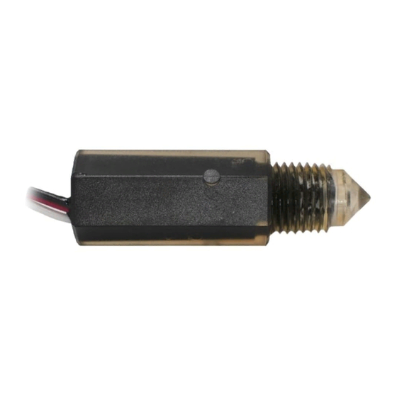
ELS-1100 Series
Power
5 VDC
10-28 VDC
(
Avoid
Sensor Type
ELS-1100 Polysulfone
ELS-1100 TFE
Variac
ELS-1100HT Isoplast
ELS-1200 RE
ELS-1200
ELS-1200CR
ELS-1100 Nylon
Note: 1 Ft-Cd = 10.7 Lux
Above testing is based on minimum readings of at
least two (2) samples.
Instruction Bulletin No. 138184 (Rev R)
Part
Input
Number
138167
144225
144235
166541
175631
187575
187590
142700
143570
143575
143577
143580
143585
143590
148973
157750
169555
169556
175632
187580
187585
Black Container
300 Ft-Cd
100 Ft-Cd
500 Ft-Cd
250 Ft-Cd
>1000 Ft-Cd
400 Ft-Cd
65 Ft-Cd
Probe Condition
At Current Sink
Wet
Wet
Wet
Wet
Wet
Wet
Dry
Wet
Dry
Dry
Wet
Wet
Wet
Dry
Dry
Wet
Wet
Dry
Dry
Dry
Wet
Opaque Container
45 Ft-Cd
25 Ft-Cd
250 Ft-Cd
25 Ft-Cd
700 Ft-Cd
25 Ft-Cd
25 Ft-Cd
Advertisement
Table of Contents

Subscribe to Our Youtube Channel
Summary of Contents for Gems ELS-1100 Series
- Page 1 4. Caution: Do not install sensor close to infrared sources or incandescent light. (Note: Any optical sensor may be affected by reflective surfaces. Consult Gems if prism is to be less than 2 inches from any reflective surface.) The test depicted below was performed to determine the sensor immunity level to ambient light. The recorded ambient is the maximum level at which the sensor performs/detects normally.
- Page 2 • Filter liquid media containing particulate and/or debris to ensure the proper operation of our products. • Selection of materials for compatibility with the media is critical to the life and operation of Gems • Electrical entries and mounting points in an enclosed tank may require liquid/vaporsealing.


Need help?
Do you have a question about the ELS-1100 Series and is the answer not in the manual?
Questions and answers