Advertisement
Quick Links
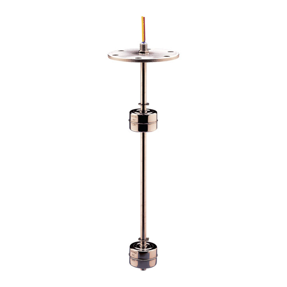
Integrated Temperature Sensors***
- Figure 1 -
- Figure 2 -
- Typical Wiring
Diagram -
Temperature
Sensor
GRN
GRN
Assembly
Level
Switch
Bottom
Temperature
of Unit
Sensor
Note: End of unit stem must be submerged a
minimum of 2-3/4" for level switch actuation.
***Note: Please use caution when handling these units, as
impact shock may damage the thermostat temperature
setting.
This product is suitable for Class I and Class II applications only, per the requirements of standard EN60730
and any additional specific requirements for a particular application or medium being sensed. Class I
compliance of metal bodied units requires a ground connection between the metal body and the earthing
system of the installation. Class I compliance of plastic bodied units in contact with a conductive medium
requires that the medium be effectively earthed so as to provide an earthed barrier between the unit and
accessible areas. For Class III compliance, a supply at safety extra-low voltage (SELV) must be provided.
Please consult the Factory for compliance information on specific part numbers.
Product must be maintained and installed in strict accordance with the
National Electrical Code and GEMS technical brochure and instruction
bulletin. Failure to observe this warning could result in serious injuries
or damages.
An appropriate explosion-proof enclosure or intrinsically safe interface
device must be used for hazardous area applications involving such
things as (but not limited to) ignitable mixtures, combustible dust and
flammable materials.
*** WARNING: To prevent ignition of flammable or combustible atmo-
spheres, disconnect power before servicing.
Pressure and temperature limitations shown on individual catalog
pages and drawings for the specified level switches must not be ex-
ceeded. These pressures and temperatures take into consideration
possible system surge pressures/temperatures and their frequencies.
P/N 154474
Rev. G
Transducer for Continuous Indication (See Figure 1)
Input: 4-30 VDC
Output: 298mA @ +77°F
Current Change: 1mA/1.8°F
Response Time: 150 Seconds (80% gradient in 60 Sec.)
Operating Range: -13°F to +221°F
Accuracy: ±2°F @ 77°F
Thermostat for Switch Actuation
(See Figure 2)
Switch Ratings: 2.6A/120V (inductive)
Contact Operation on Increasing Temperature:
"Opens" when set point reached - or -
"Closes" when set point reached
Standard Temperature Set Point (±10°F):
100°F, 125°F, 150°F, 175°F, 200°F or 225°F
Switch Ratings - Maximum Resistive Load
(LS-700 and LS-700-EP Series)
VA
Volts
Amps (AC)
0-50
.2
10
120
.08
General Use
100
N.A.
0-30
.4
20
120
.17
Pilot Duty
240
.08
0-50
0.5
50
120
.4
General Use
240
.2
**
120
.8
*
100
240
.4
*Level switch units with 100 VA switches are not U.L. recognized.
**Limited to 50,000 operations
Important Points!
Selection of materials for compatibility with the media is critical to
the life and operation of GEMS level switches. Take care in the
proper selection of materials of construction; particularly wetted
materials.
Life expectancy of switch contacts varies with applications. Contact
GEMS if life cycle testing is required.
Ambient temperature changes do affect switch set points, since the
specific gravity of a liquid can vary with temperature.
Level switches have been designed to resist shock and vibration; how-
ever, shock and vibration should be minimized.
Liquid media containing particulate and/or debris should be filtered to
ensure proper operation of GEMS products.
Electrical entries and mounting points may require liquid/vapor seal-
ing if located in an enclosed tank.
Level switches must not be field repaired.
Physical damage sustained by the product may render it unservice-
Installation...
Install LS-700 and LS-700-EP Series switches vertically in tank top (mounting up) or in tank bottom (mounting down). Multi-station
level switches will operate normally inclined up to 30
LS-700 Series Mounting Types...
Each mounting type can be configured with stem lengths (Lo) and float materials
indicated in table below.
Amps (DC)
.13
N.A.
.3
.3
.13
.06
0.5
.4
.2
N.A.
Stem and Mounting
N.A.
Material
Max. Length
Mounting Position
Float Stops
Pressure Rating,
*
.
PSI, Max
*
Mounting only. Maximum pressure rating for complete unit will be the lowerof this pressure or the selected float pressure
(See Float Types, below)
Float Types...LS-700 Series ONLY
Float Material
Compatible Mtg Types
Float Dimensions
Part Number
Operating Temp.
Pressure, PSI, Max.
Min. Liquid S.G.
**
Derated with Increasing Temperature
***
Standard Construction
****
Ceramic Potting Construction Required
Series LS-700, 700-EP
Multi-Station Level Switches
Instruction Bulletin No. 154474
(Includes LS-700's with Temperature Sensors)
o
.
Type 1
Type 2
Type 3
Type 5
1/8" NPT
3/4" NPT
1" NPT
1-5/16" - 12UNF-2A
1-5/16"
1-1/2"
1/2"
1-1/16"
HEX
HEX
HEX
HEX
Neoprene
O-Ring
Brass or 316 Stainless Steel
48 Inches (121.9 cm)
Vertical ± 30° Inclination
Brass Units: Beryllium Copper Grip Rings; Stainless Steel Units: S.S. ARMCO PH-15-7MO Grip Rings
See Float Values Below
(A single float type is selected for use at all actuation points)
Buna N
1, 2, 3, 4,5,6
1, 3, 4,5,6
↓
↑
15/16"
1-1/4"
(23.8 mm)
(31.7. mm)
↑
↓
← ← ← ← ←
→ → → → →
1" Dia.
29/32" Dia.
→ → → → →
← ← ← ← ←
(25.4 mm)
(23.0 mm)
138030
39049
Water: to 180
o
F (82.2
o
C)
Oil: -40
o
F to +250
o
F
Oil: -40
o
F to +250
o
F
(-40
C to +121.1
C)
o
o
(-40
o
C to +121.1
o
C)
*
*
300
250
.45
.60
Type 4
3-5/8" Dia. Flange
Bolt Circle
3" Dia.
↑
(76.2 mm)
Type 6
3-5/8" dia.
3/8"-24
(92.1 mm)
5/16" Dia.
↓
(7.9 mm)
1/2"
Thru (6)
HEX
1/8"
Holes
3/16"
NPT
(4.8 mm)
↓
↑
50
Teflon - Spring Biased
316 Stainless Steel
1, 2, 3, 4, 5, 6
1, 4, 6
↓
↑
1-3/32"
1"
(27.8 mm)
(25.4 mm)
↓
↑
→ → → → →
Spring Bias
1-1/2" Dia.
← ← ← ← ←
→ → → → →
← ← ← ← ←
29/32" Dia.
(38.1 mm)
(23.0 mm)
133764
60241
***
-40
F to +300
F
o
o
-40
o
F to +300
o
F
(-40
o
C to +148.9
o
C)
(-40
C to +148.9
C)
o
o
301°F to 500°F****
**
1000
100
.65
.70
More Float Types
Advertisement

Related Manuals for Gems LS-700 Series


Summary of Contents for Gems LS-700 Series
- Page 1 Selection of materials for compatibility with the media is critical to National Electrical Code and GEMS technical brochure and instruction the life and operation of GEMS level switches. Take care in the bulletin. Failure to observe this warning could result in serious injuries proper selection of materials of construction;...
- Page 2 Typical Wiring Diagram Wiring Color Code Float Types (LS-700 Series - Cont.) For clarity, only two actuation levels are shown in Tinted Area Designates U.L. each group Recognized Wiring Configurations 304 Stainless Steel 316 Stainless Steel Float Material SPST Switches...
Need help?
Do you have a question about the LS-700 Series and is the answer not in the manual?
Questions and answers