Table of Contents
Advertisement
Advertisement
Table of Contents

Related Manuals for Torus Power AVR2 ELITE Series


Summary of Contents for Torus Power AVR2 ELITE Series
- Page 1 AVR2 ELITE Series Owner’s Manual...
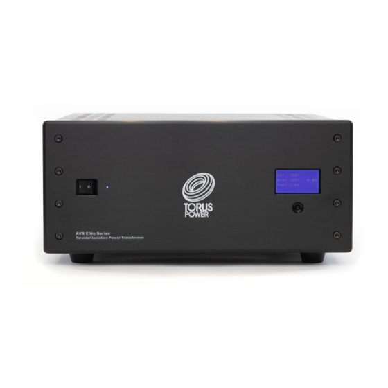
- Page 2 Torus Power toroidal isolation transformers dramatically improve the performance of all audio and video systems. Connect audio equipment to a Torus Power isolation transformer and it comes alive - with more dynamics, improved imaging, and cleaner, enhanced bass. Video is crisper, with darker blacks, and brighter colours.
-
Page 3: Table Of Contents
Table of Contents IMPORTANT SAFETY INSTRUCTIONS ..........................1 Shipping Carton & Packing Material ..........................3 Placement & Ventilation............................... 3 Torus Power AVR ELITE SERIES Overview ........................4 Front Panel Display ............................... 5 Voltage Fault Protection ............................... 6 Notes: ................................. 7 Component Connection Zones ............................. -
Page 4: Important Safety Instructions
IMPORTANT SAFETY INSTRUCTIONS CAUTION! To reduce the risk of electric shock and fire, do not remove the cover of this device. There are no user serviceable parts inside. Please refer all servicing to licensed service technicians. CAUTION! The international symbol of a lightning bolt inside a triangle is intended to alert the user to uninsulated “dangerous voltage”... - Page 5 The power switch should be in the “off” position when connecting or disconnecting equipment from a Torus Power unit. CAUTION Some units can be very heavy, please use safe practices when lifting. P a g e...
-
Page 6: Shipping Carton & Packing Material
Ship the unit only in the original packing material, as the unit is not insurable by carriers otherwise. Placement & Ventilation Torus Power PIUs (Power Isolation Units) are extremely efficient yet very high power devices, and must be adequately cooled. -
Page 7: Torus Power Avr Elite Series Overview
Torus Power AVR ELITE SERIES Overview Torus Power AVR ELITE models deliver clean AC power with noise attenuation from 2 KHz to beyond 1 MHz. They provide true isolation (using large toroidal transformers) along with low source impedance and high instantaneous current for today’s most sophisticated and powerful audio amplifiers. -
Page 8: Front Panel Display
Front Panel Display The front panel consists of a 4 line LCD display and a pushbutton switch. Each time you push the button the display will show a different feature of the AVR ELITE. When you first turn on the AVR ELITE the System Status will appear. Each time you push the button it will change from one information screen to another. -
Page 9: Voltage Fault Protection
Voltage Fault Protection If the AC voltage supplied to the AVR ELITE is too high or too low voltage (see reference chart at the end of this section) for 1 second or more, a voltage fault message is displayed and the back panel fault output is turned on. -
Page 10: Notes
Notes: ON at all times for series mode surge protection to be The AVR ELITE unit needs to be switched active. If the AVR ELITE and connected components will not be used for an extended period of time, it is recommended to unplug the AVR ELITE unit from main power. There is a 20-second delay built into the AVR ELITE system, to prevent nuisance switching. -
Page 11: Component Connection Zones
• Each zone can be scheduled to turn ON or OFF at any time or day of the week. • Each zone can also be individually turned ON or OFF through the local web browser interface or Torus Power Connect account •... -
Page 12: Rear Panel Connections
Ethernet Allows access to the AVR ELITE and internal software via a local web browser interface (See AVR ELITE software section for more details) or Torus Power Connect service (see Torus Power Connect section). USB 2.0 Port For charging and external control (future) 12VDC Trigger On/Off The AVR ELITE can be turned on and off by a 12 volt trigger input. -
Page 13: Circuit Schematics
Circuit Schematics North American Model (AVR2 ELITE 20) 10 | P a g e... - Page 14 North American Model (AVR2 ELITE 40 BAL) International Model (AVR2 ELITE 16 CE) 11 | P a g e...
-
Page 15: Avr Elite Embedded Software
AVR ELITE Embedded Software The AVR ELITE local area network web browser interface is resident in the microprocessor on the internal control board. There are two methods to access the software. Connect the AVR ELITE Ethernet port to a local network port and open a web browser on a PC that is connected to the same local network. -
Page 16: Avr Elite Menu Selections
AVR ELITE Menu Selections System Status This screen indicates the overall status of the system, showing Voltage In, Voltage Out, Current Out, Power Consumption and Active Zones. It also reports if the system is functioning normally or whether there is a fault condition. (No password required to monitor status) Switch Main Power This screen allows ON/OFF control of the AVR... - Page 17 Zone Power Control The current ON/OFF state of each zone is indicated here. Each zone can be individually turned on or off. Use the ‘ON’ and ‘OFF’ buttons to change the zone state. Press ‘SET’ to save the new settings. Active zones are also shown in the front panel display.
- Page 18 System Setup Delay Time Between Zones (Scheduler and Start UP): Select a delay interval time (1 to 999 seconds) for sequential Power ON and OFF between zones. Schedule: By checking this button the output zones will follow the defined schedules for turning power on or off.
- Page 19 Some networks require each PC or device to use a fixed IP address and the AVR ELITE also supports this option. The WiFi section is required when using the Torus Power Connect service. Change Password If you wish to change the password, use this screen.
- Page 20 North American Models Electrical Specifications Input Voltage Output Voltage Maximum Available Number of IP Model Number Input Fuses Nominal Nominal Output Current Addressable Zones 120VAC, 60Hz AVR2 ELITE 20 1 x 20A 4 + R (Operating Range 120VAC ± 4V 85V to 135V) AVR2 ELITE 40 BAL 2 x 20A...
- Page 21 International Models Electrical Specifications Input Voltage Output Voltage Input Circuit Maximum Available Number of IP Model Number Nominal Nominal Breaker (Fuses) Output Current Addressable Zones AVR2 ELITE 8 CE 1 x 8A 4 + R 240VAC, 50/60Hz 220-240VAC ± 8V AVR2 ELITE 16 CE (Operating Range 1 x 16A...
- Page 22 Input Connector Output Connector Size, mm (WxDxH) Weight Chassis Model Number Line Cord (Rear Panel) (Rear Panel) Size, inch (WxDxH) KG(lb) Height 10A/250VAC, 2.5M IEC 15A Inlet, 10A/250V 483x483x203 AVR2 ELITE 8 AUS Plug: AS/NZS 3112:2000 38.5(85) 4U (7.00”) NEMA C14 AUS Socket (x6) 17x19x8 Connector - IEC C13...
- Page 23 Factory Reset Procedure 1. Disconnect the Ethernet cable from the AVR. 2. Turn the power switch to the OFF position. The power light will go out. 3. Press and hold the little pushbutton switch below the front panel display on the AVR. 4.
-
Page 24: Torus Power Connect
Torus Power Connect provides Users with a custom dashboard for control, status, setup, and configuration purposes. One year of Torus Power Connect service is included with each new AVR Elite purchase. A subscription renewal is required to continue this service beyond the first year. Visit www.toruspower.com... -
Page 25: User Registration
Register Account. A temporary password will be sent to the email address provided. The User must login to the Torus Power Connect web site (www.toruspowerconnect.com) within 30 days to set a new secure password and activate their Torus Power Connect account. -
Page 26: User Menu
User Menu The Torus Power Connect User login defaults to the Live Data screen (see Present Live Data for details). Click on User Menu to see a dropdown list of available options. Highlight and click to select the desired option (see below for details of each option) -
Page 27: Live Data
Live Data Click the Present text for a specific AVR Elite device to easily view its input voltage, output voltage, input current, output current, and output Total Harmonic Distortion values. Clicking the Refresh text bar will update the Live Data details every 3 seconds for 1 minute. 24 | P a g e... -
Page 28: Power Control
Power Control Click the Control text for a specific AVR Elite device to manually control (ON/OFF) the unit’s power state or the power state of each individual outlet zone. Click the Refresh Reported Values text to confirm the specific action was successful. 25 | P a g e... -
Page 29: System Setup
System Setup Click the Setup text for a specific AVR Elite device to view and edit operational setting of the device. Click Save Setup text bar for changes to be saved on the AVR Elite. • Out of Range Voltage – when this box is checked the AVR Elite will automatically turn off when the incoming voltage is above or below the acceptable range. - Page 30 27 | P a g e...
-
Page 31: Historical Charts
Historical Charts Click the Plot text for a specific AVR Elite device to Move the mouse cursor to one of the plot points to get the value and time for that data point. 28 | P a g e... - Page 32 29 | P a g e...
-
Page 33: Historical Data
Historical Data Click the Retrieve text for a specific AVR Elite device to get a listing of voltage, current, total harmonic distortion, and voltage regulation values based on the date and time period entered. The Requested Time entered is the time for the first data values and the Requested Interval is the time period duration to be provided. - Page 34 31 | P a g e...
-
Page 35: Schedule
Schedule Click the Manage text for a specific AVR Elite device to define specific times of each day to automatically turn on and off power for each output zone individually. The Schedule box under Setup System must be checked for any defined schedule to apply. To create a scheduled power on or off click the desired day, then type in the hour and minutes (24 hour format) or use the up/down arrows to scroll to the desired value. - Page 36 33 | P a g e...
-
Page 37: Report
Report Click the Send text for a specific AVR Elite device to email system event details for the specified time period. It can be sent as a CSV format file or a fixed format pdf file. The CSV format file can be imported into a spreadsheet software program such as Microsoft Excel so it can be manipulated to filter/present the information in the desired format. -
Page 38: Personal Information
The Personal Information home screen shows the User’s contact information submitted during the Torus Power Connect registration. The User can use the Change Password text bar at any time to submit a new Torus Power Connect login password. 35 | P a g e...
Need help?
Do you have a question about the AVR2 ELITE Series and is the answer not in the manual?
Questions and answers