Advertisement
Table of Contents
MJE-EXL200 No.0071-60V
Thank you very much for purchasing Panasonic products.
Please read this Instruction Manual carefully and thor-
oughly for the correct and optimum use of this product.
Kindly keep this manual in a convenient place for quick
reference.
WARNING
Never use this product as a sensing device for per-
sonnel protection.
In case of using sensing devices for personnel
protection, use products which meet laws and stan-
dards, such as OSHA, ANSI or IEC etc., for person-
nel protection applicable in each region or country.
uct" by IEC / JIS standard, GB standard and FDA.
Do not look the laser directly. Lasers are potentially
hazardous. Furthermore, do not view the laser
Never disassemble, repair or modify the product.
In case of control or adjustment using procedures
al, hazardous laser radiation exposure can result.
In order to prevent the accident by laser product and
protect the users, JIS C 6802
-2014
products" was established based on the regulation
of IEC (International electrotechnical Commission).
This regulation classifies laser products according
to the level of hazard, and provides the safety mea-
sures for respective classes.
" according to IEC 60825-1
) "Safety of laser products".
2014
This product complies with 21 CFR 1040.10 and
1040.11 based on Laser Notice No. 50, dated June
24, 2007, issued by CDRH (Center for Devices and
Radiological Health) under FDA (Food and Drug Ad-
ministration).
For details, refer to the Laser Notice No. 50.
6802
)
-2014
Description
Class 1
Safe under reasonably foreseeable conditions.
•
the IEC 60825-1
standard.
-2014
Warning label
/
2
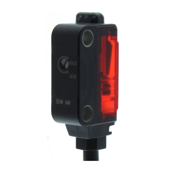
Stability indica-
Operation indicator
tor (Green)
(Orange) (Note 2)
(Note 1)
Lights up when the
Lights up un-
output is ON
der the stable
light condition
or the stable
dark condition
Notes: 1) Not incorporated on the emitter of thru-beam type.
2) It is the power indicator (Green: lights up when the power is ON) for
the emitter of thru-beam type.
3) It is not incorporated in emitter of
It is not incorporated in
.
3
In case mounting this device, use the metal plate
beam misalignment may occur. Also, install the metal
plate in between the sensor and the mounting surface.
The tightening torque should be 0.5N·m or less with
M3 screws.
13mm
t0.8mm
8.2mm
In case using the dedicated sensor mounting bracket
-
(optional) when mounting this device, the metal plate
the mounting direction. Mount as the diagram below
indicates.
-
Accessory of the sensor
mounting bracket
"Safety of laser
Sensor mounting
bracket (Optional)
-
(JIS C 6802
-2014
-
Accessory of the sensor
mounting bracket
(JIS C
-2014
Sensor mounting
bracket (Optional)
In case not using the metal plate
cessory) when mounting this product, work on the
mounting hole as the diagram below indicates.
Tapping for M3 screw
A
No chamfering and
no burr on mount-
ing surface.
After mounting the thru-beam type, be sure to adjust
light axis of the emission spot to hit the center of the
reciever.
Sensitivity
adjuster
(Note 3, 4)
Center of receiver
Emission spot
.
(accessory).Without using the metal plate,
Metal plate
Metal plate
(Accessory)
(Accessory)
16mm
t0.8mm
8.2mm
M3 screw
(Purchase separately)
(accessory) is required depending on
Metal plate
(Accessory)
M3 (length: 14mm) screw with washer
(Accessory of the sensor mounting bracket)
Metal plate
(Accessory)
M3 (length: 14mm) screw with washer
(Accessory of the sensor mounting bracket)
(ac-
2-ø3.05 ±0.05mm
Type
A
13±0.05mm
A
16±0.05mm
Chamfering
Burr
Chamfering on
Burr on mounting
mounting surface.
surface.
4
WIRING
Make sure to use the cable with connector,
(optional), when connecting to the pig-
tailed type.
Tighten the fixing ring of the cable with connector
completely by hand when mounting. (The tightening
torque: 0.2N·m)
it may cause connector damage.
If the tightening is not enough, the fixing ring may
loosen due to vibration, etc.
Insert the cable with connector into a connecting
Cable with connector
(Optional)
Fixing ring
Fixing ring
ened. If the cable is pulled by excessive force (15N or more) when the
5
(Brown) +V
(Pink) Output
operation switching
input (Note 1, 2)
(Black) Output (Note 1)
50mA max.
(Blue) 0V
(Brown) +V
50mA max.
(Black) Output (Note 1)
(Pink) Output
operation switching
input (Note 1, 2)
(Blue) 0V
Notes: 1) The emitter of thru-beam type dose not incorporate output (black)
and output operation switching input (pink).
2) Be able to select either Light-ON or Dark-ON by wiring the output
operation switching input (pink) as a following table.
Light-ON
Thru-beam type
Wire to 0V
Wire to +V or Open
1
3
Terminal name
1
+V
2
Input operation switching input (Note)
3
0V
4
4
Output (Note)
2
Note: The emitter of thru-beam type dose not incorporate output and output
operation switching input.
Pigtailed type
-
-
Load
+
-
+
-
Load
Dark-ON
Wire to +V or Open
Wire to 0V
Advertisement
Table of Contents

Related Manuals for Panasonic EX-L200 Series


Summary of Contents for Panasonic EX-L200 Series
- Page 1 M3 screws. torque: 0.2N·m) MJE-EXL200 No.0071-60V it may cause connector damage. Thank you very much for purchasing Panasonic products. If the tightening is not enough, the fixing ring may Metal plate Metal plate Please read this Instruction Manual carefully and thor- loosen due to vibration, etc.
- Page 2 CN-24A-C2 (Cable length : 2m), CN-24A-C5 (Cable length : 5m) (Cable length : 2m), (Cable length : 5m) Panasonic Industrial Devices SUNX Co., Ltd. https://panasonic.net/id/pidsx/global Please visit our website for inquiries and about our sales network. © Panasonic Industrial Devices SUNX Co., Ltd. 2020 PRINTED IN JAPAN...
Need help?
Do you have a question about the EX-L200 Series and is the answer not in the manual?
Questions and answers