Table of Contents
Advertisement
Quick Links
Advertisement
Table of Contents

Related Manuals for ABB ACS880-01+C135 Series


Summary of Contents for ABB ACS880-01+C135 Series
- Page 1 — ABB DRIVES ACS880-01…+C135 drives with flange mounting kit Supplement...
- Page 2 —...
- Page 3 ACS880-01…+C135 drives with flange mounting kit Supplement Table of contents 3. Mechanical installation 2019 ABB Oy. All Rights Reserved. 3AXD50000349814 Rev A EFFECTIVE: 2019-04-16...
-
Page 5: Table Of Contents
Table of contents 5 Table of contents 1. Introduction to the supplement Contents of this chapter ............7 Applicability . - Page 6 6 Table of contents 4. Dimension drawings Contents of this chapter ........... . . 45 Frame R1 .
-
Page 7: Introduction To The Supplement
Introduction to the supplement 7 Introduction to the supplement Contents of this chapter This chapter describes the supplement. Applicability This supplement applies to ACS880-01 drive with flange mounting kits (option +C135). Target audience This supplement is intended for people who plan the installation and install the drive with the flange mounting kit. -
Page 8: Related Documents
Document library on the Internet on the inside of the back cover. For manuals not available in the Document library, contact your local ABB representative. The code below opens an online listing of the manuals applicable to the product. ACS880-01 manuals... -
Page 9: Hardware Description
Hardware description 9 Hardware description Contents of this chapter This chapter describes the flange mounting kit. Product overview The flange mounting kit contains brackets for attaching the drive onto a mounting plate. The heat sink of the drive can be located in the cooling air channel and the front part on the other side of the mounting plate. -
Page 10: Tilted Position, R1 To R5
10 Hardware description Tilted position, R1 to R5 Mounting plate Top flange bracket Lifting hole Side flange bracket Cable shelf Bottom flange bracket Drive heat sink in the cooling air channel... -
Page 11: Upright Position, R6 To R9
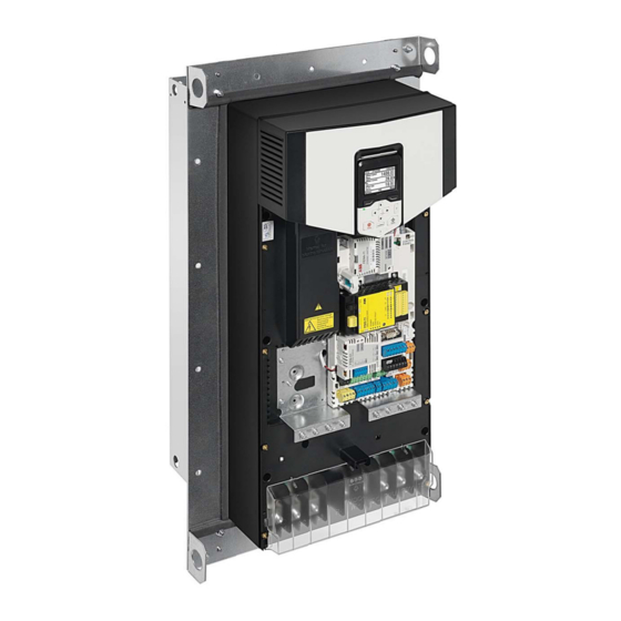
Hardware description 11 Upright position, R6 to R9 Hood (in the cooling air channel; required for UL Type 12) Top flange bracket Mounting plate Lifting hole Drive heat sink in the cooling air channel Side flange bracket Drive front side Bottom flange bracket Degree of protection This table shows the degree of protection of the flange-mounted drive. -
Page 12: Special Requirements
12 Hardware description Special requirements Frame size Special requirement Insert sealing plug. Insert sealing plug and attach sealing tapes. Ordering codes The flange mounting kit is a plus code option (+C135) or can be ordered with these ordering codes also separately. Frame size Ordering code 3AXD50000024175... -
Page 13: Mechanical Installation
Mechanical installation 13 Mechanical installation Contents of this chapter This chapter describes how to install the drive with the flange mounting kit mechanically. Safety Obey the general safety instructions in the hardware manual and the task-specific instructions in this supplement. Wear protective gloves and long sleeves. -
Page 14: Examining The Installation Site
14 Mechanical installation Examining the installation site Make sure that the installation site agrees with these requirements: • The installation site has sufficient ventilation to prevent overheating of the drive. See section Losses, cooling data and noise in the hardware manual for the required air flow in the cooling air channel and in the front part of the drive. -
Page 15: Frames R1 To R5
Mechanical installation 15 Frames R1 to R5 Item Description Item Description Straps Cardboard sleeve Printed manuals and quick guides, 6…7 Cushions manuals CD and multilingual residual voltage warning stickers Cardboard cover Drive with factory installed options Flange mounting kit Cardboard tray To unpack: •... -
Page 16: Frames R6 To R9
16 Mechanical installation Frames R6 to R9 Item Description Item Description Straps Drive with factory installed options Cardboard cover Pallet stopper Flange mounting kit Pallet tray Cardboard sleeve Printed manuals and quick guides, manuals CD and multilingual residual voltage warning stickers To unpack: •... -
Page 17: Flange Mounting Kit Package Contents
Mechanical installation 17 Flange mounting kit package contents The illustrations show the layout of the flange mounting kit packages. Examine that all items are present and there are no signs of damage. Frames R1 to R3 Quick guide Cable shelf Top bracket Grounding plate Bottom bracket... -
Page 18: Frames R4 To R5
18 Mechanical installation Frames R4 to R5 Quick guide Mounting template Bottom bracket Top bracket Side brackets Cardboard tray Sealing plug Top cardboard cover Option kit package label Screw package: • M6 nut (14 pcs) * • M6×20 screw (2 pcs) •... -
Page 19: Frames R6 To R9
Mechanical installation 19 Frames R6 to R9 Quick guide Mounting template Top bracket Bottom bracket Side brackets Top cardboard cover Option kit package label Screw package: • M6 nut (11 pcs) * • M6×10 T30 (12 pcs) • M6×25 T25 (R6…R8: 16 pcs, R9: 18 pcs) Hood (required for UL Type 12) Cardboard tray... -
Page 20: Installing The Drive
20 Mechanical installation Installing the drive Free space requirements The flange-mounted drives can be installed side by side. Free space requirements above and below the drive are shown below. 200 mm (7.87 in) 300 mm (11.81 in) -
Page 21: Installing Drives Above One Another
Mechanical installation 21 Installing drives above one another Make sure that the outlet cooling air flows away from the drive above. 200 mm (7.87 in.) 120 mm (4.72 in.) 250 mm 120 mm (9.84 in.) (4.72 in.) 300 mm (11.81 in.) -
Page 22: Installation Procedure
22 Mechanical installation Installation procedure Frames R1 to R3 1. To remove the fan assembly, push the retaining clip with a flat screwdriver. Lift the assembly up. - Page 23 Mechanical installation 23 2. Insert the sealing plug to the hole shown in the figure. 3. Reinstall the fan assembly in reverse order.
- Page 24 24 Mechanical installation 4. Attach the top and bottom U-brackets to the drive. 4 × M5 nut 6 N·m...
- Page 25 Mechanical installation 25 5. First attach the side brackets (a) to the top and bottom U-brackets with four M6 nuts. Then, attach the tightening brackets (b) to the both ends with four M5×20 screws. Last attach the sealing plate (c) to the bottom of the drive with two M5×50 screws T20.
- Page 26 26 Mechanical installation 6. Attach the top and bottom brackets to the side brackets. 8 × M6 nut 10 N·m...
- Page 27 Mechanical installation 27 7. Push the grounding plate (d) onto the alignment pins of the bottom bracket and attach it to the drive with one M5×25 screw T20 and three M6 nuts. Then attach the cable shelf (e) to the bottom bracket with two M6 nuts. 5 ×...
- Page 28 28 Mechanical installation 8. See chapter Dimension drawings for the dimensions of the flange and the required opening in the mounting plate. Attach the mounting template from the flange mounting kit package onto the mounting plate. Make the opening and drill the holes for the mounting screws. Consider the hole size for the Rivet or Kalei nuts (not included in the delivery).
- Page 29 Mechanical installation 29 9. Attach chains to the drive lifting holes and lift the drive with a lifting device onto the opening in the mounting plate. 10. Attach the bottom bracket with one screw. 1 × M6×25 screw 10 N·m...
- Page 30 30 Mechanical installation 11. Attach the top bracket with one screw. 1 × M6×25 screw 10 N·m 12. Attach the rest of the mounting screws. Remove the chains. 8 × M6×2 screw 10 N·m...
-
Page 31: Frames R4 To R5
Mechanical installation 31 Frames R4 to R5 1. To remove the fan assembly, lift the fan mounting plate up from the front edge. Unplug the fan power supply wires. Lift the assembly off. 2. Insert the sealing plug to the hole shown in the figure. - Page 32 32 Mechanical installation 3. Reinstall the fan assembly in reverse order. 4. Attach the sealing tapes on both sides of the drive.
- Page 33 Mechanical installation 33 5. Attach the side brackets to the drive. Note that R4 has 6 screws for attaching the side brackets while R5 has 8 screws. R4: 6 × M6×10 screw T30 R5: 8 × M6×10 screw T30 8 N·m 6.
- Page 34 34 Mechanical installation 7. Attach the top bracket to the side brackets. 4 × M6 nut 10 N·m 8. Attach the cable shelf to the bottom bracket. 3 × M6 nut 10 N·m...
- Page 35 Mechanical installation 35 9. See chapter Dimension drawings for the dimensions of the flange and the required opening in the mounting plate. Attach the mounting template from the flange mounting kit package onto the mounting plate. Make the opening and drill the holes for the mounting screws. Consider the hole size for the Rivet or Kalei nuts (not included in the delivery).
- Page 36 36 Mechanical installation 10. UL Type 12 installation only: Attach the hood to the cooling channel. 3 × M6 nut 10 N·m Back Front Back Front Back: View from top Back: View from bottom...
- Page 37 Mechanical installation 37 11. Attach chains to the lifting holes of the flange and lift the drive with a lifting device onto the opening in the mounting plate. 12. Attach the top bracket with one screw. 1 × M6×25 10 N·m...
- Page 38 38 Mechanical installation 13. Attach the bottom bracket with one screw. 1 × M6×25 10 N·m 14. Attach the rest of the mounting screws. Remove the chains. 12 × M6×25 10 N·m...
- Page 39 Mechanical installation 39 For instructions on installing an auxiliary cooling fan to drives with front cover on, see chapter Maintenance in the hardware manual.
-
Page 40: Frames R6 To R9
40 Mechanical installation Frames R6 to R9 1. Attach the side brackets of the flange to the drive. 12 × M6×10 T30 6 N·m 2. Attach the top and bottom brackets. 8 × M6 nut 6 N·m... - Page 41 Mechanical installation 41 3. See chapter Dimension drawings for the dimensions of the flange and the required opening in the mounting plate. Attach the mounting template from the flange mounting kit package onto the mounting plate. Make the opening and drill the holes for the mounting screws. Consider the hole size for the Rivet or Kalei nuts (not included in the delivery).
- Page 42 42 Mechanical installation 4. UL Type 12 installation only: Attach the hood to the cooling channel. 3 × M6 nut 6 N·m Back Front Back: View from top Back: View from bottom 5. Attach chains to the lifting holes of the flange and lift the drive with a lifting device onto the opening in the mounting plate.
- Page 43 Mechanical installation 43 6. Attach the bottom bracket with one screw. 1 × M6×25 6 N·m 7. Attach the top bracket with one screw. 1 × M6×25 6 N·m...
- Page 44 44 Mechanical installation 8. Attach the rest of the mounting screws. Remove the chains. R6…R8: 14 × M6×25 6 N·m 16 × M6×25 6 N·m...
-
Page 45: Dimension Drawings
Dimension drawings 45 Dimension drawings Contents of this chapter This chapter contains the dimension drawings of the flange mounting kits and required openings in the mounting plate. For the dimensions of the drive, see the hardware manual. -
Page 46: Frame R1
46 Dimension drawings Frame R1... -
Page 47: Attaching Points And Opening Dimensions
Dimension drawings 47 Attaching points and opening dimensions 3AXD50000024858... -
Page 48: Frame R2
48 Dimension drawings Frame R2... -
Page 49: Attaching Points And Opening Dimensions
Dimension drawings 49 Attaching points and opening dimensions 3AXD50000024859... -
Page 50: Frame R3
50 Dimension drawings Frame R3... -
Page 51: Attaching Points And Opening Dimensions
Dimension drawings 51 Attaching points and opening dimensions 3AXD50000024860... -
Page 52: Frame R4
52 Dimension drawings Frame R4... - Page 53 Dimension drawings 53 Hood is needed for UL Type 12 installation only...
-
Page 54: Attaching Points And Opening Dimensions
54 Dimension drawings Attaching points and opening dimensions 3AXD50000027190... -
Page 55: Frame R5
Dimension drawings 55 Frame R5... - Page 56 56 Dimension drawings Hood is needed for UL Type 12 installation only...
-
Page 57: Attaching Points And Opening Dimensions
Dimension drawings 57 Attaching points and opening dimensions 3AXD50000018602... -
Page 58: Frame R6
58 Dimension drawings Frame R6... - Page 59 Dimension drawings 59 Hood is needed for UL Type 12 installation only...
-
Page 60: Attaching Points And Opening Dimensions
60 Dimension drawings Attaching points and opening dimensions 3AXD50000019323... -
Page 61: Frame R7
Dimension drawings 61 Frame R7... - Page 62 62 Dimension drawings Hood is needed for UL Type 12 installation only...
-
Page 63: Attaching Points And Opening Dimensions
Dimension drawings 63 Attaching points and opening dimensions 3AXD50000019324... -
Page 64: Frame R8
64 Dimension drawings Frame R8... - Page 65 Dimension drawings 65 Hood is needed for UL Type 12 installation only...
-
Page 66: Attaching Points And Opening Dimensions
66 Dimension drawings Attaching points and opening dimensions 3AXD50000019325... -
Page 67: Frame R9
Dimension drawings 67 Frame R9... - Page 68 68 Dimension drawings Hood is needed for UL Type 12 installation only...
-
Page 69: Attaching Points And Opening Dimensions
Dimension drawings 69 Attaching points and opening dimensions 3AXD50000019326... - Page 70 70 Dimension drawings...
-
Page 71: Mounting Examples
Mounting examples 71 Mounting examples Contents of this chapter This chapter contains flange mounting examples in a cooling channel. -
Page 72: Frame R1
72 Mounting examples Frame R1... - Page 73 Mounting examples 73...
- Page 74 74 Mounting examples...
-
Page 75: Frame R2
Mounting examples 75 Frame R2... - Page 76 76 Mounting examples...
- Page 77 Mounting examples 77...
-
Page 78: Frame R3
78 Mounting examples Frame R3... - Page 79 Mounting examples 79...
- Page 80 80 Mounting examples...
-
Page 81: Frame R4
Mounting examples 81 Frame R4... - Page 82 82 Mounting examples...
- Page 83 Mounting examples 83...
-
Page 84: Frame R5
84 Mounting examples Frame R5... - Page 85 Mounting examples 85...
- Page 86 86 Mounting examples...
-
Page 87: Frame R6
Mounting examples 87 Frame R6... - Page 88 88 Mounting examples...
- Page 89 Mounting examples 89...
-
Page 90: Frame R7
90 Mounting examples Frame R7... - Page 91 Mounting examples 91...
- Page 92 92 Mounting examples...
-
Page 93: Frame R8
Mounting examples 93 Frame R8... - Page 94 94 Mounting examples...
- Page 95 Mounting examples 95...
-
Page 96: Frame R9
96 Mounting examples Frame R9... - Page 97 Mounting examples 97...
- Page 98 98 Mounting examples...
- Page 99 Address any inquiries about the product to your local ABB representative, quoting the type designation and serial number of the unit in question. A listing of ABB sales, support and service contacts can be found by navigating to abb.com/searchchannels. Product training For information on ABB product training, navigate to new.abb.com/service/training.
- Page 100 © Copyright 2019 ABB. All rights reserved. Specifications subject to change without notice.
Need help?
Do you have a question about the ACS880-01+C135 Series and is the answer not in the manual?
Questions and answers