
Related Manuals for Alpha Technologies CXPS-E3 19


Summary of Contents for Alpha Technologies CXPS-E3 19
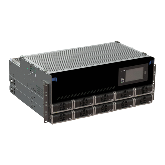
- Page 1 CXPS-E3 200A - 400A Power System Technical Guide: 9400016-J0 Effective: 05/2019 Alpha Technologies Ltd.
- Page 3 International: +1-604-436-5547 Copyright Copyright © 2019 Alpha Technologies Ltd. All rights reserved. Alpha is a registered trademark of Alpha Technologies. No part of this documentation shall be reproduced, stored in a retrieval system, translated, transcribed, or transmit- ted in any form or by any means manual, electric, electronic, electromechanical, chemical, optical, or otherwise without prior explicit written permission from Alpha Technologies.
-
Page 4: Table Of Contents
Table of Contents 1. Safety ............................6 1.1 Safety Symbols .......................... 6 1.2 General Warning and Cautions ....................6 1.3 Electrical Safety ......................... 7 1.4 Battery Safety ..........................7 2. Introduction ...........................8 2.1 Scope of the Manual ........................8 2.2 Product Overview ........................8 2.3 ... - Page 5 6.5 Power System Assembly and Mounting ................... 25 6.6 Breaker Installation ........................27 7. Wiring ..........................28 7.1 Installation Notes ........................28 7.2 Grounding ..........................29 7.3 AC Wiring ..........................32 7.4 DC Wiring ..........................33 7.5 Distribution Cabling ........................34 7.6 Alarm and Signal Connection ....................
- Page 6 List of Figures Figure 1 — CXPS-E3 System ......................8 Figure 2 — 19" CXPS-E3 with 48-2.4kW Rectifiers ................9 Figure 3 — 23" CXPS-E3 with 48-2.4kW Rectifiers ................9 Figure 4 — 19" CXPS-E3 with 48-4.0kW Rectifiers ................ 10 Figure 5 — 23" CXPS-E3 with 48-4.0kW Rectifiers ................ 10 Figure 6 — Front Panel w/ L-ADIO and CXC HP Controller ............14 Figure 7 —...
-
Page 7: Safety
Keep it in a safe place. Review the drawings and illustrations contained in this manual before proceeding. If there are any questions regarding the safe installation or operation of this product, contact Alpha Technologies or the nearest Alpha representative. 1.1 Safety Symbols To reduce the risk of injury or death, and to ensure the continued safe operation of this product, the following sym- bols have been placed throughout this manual. -
Page 8: Electrical Safety
1.3 Electrical Safety WARNING! Hazardous voltages are present at the input of power systems. The DC output from rec- tifiers and batteries, though not dangerous in voltage, has a high short-circuit current capacity that may cause severe burns and electrical arcing. •... -
Page 9: Introduction
2. Introduction 2.1 Scope of the Manual This manual covers the features, options, installation and startup of Alpha Technologies CXPS-E3 power system. Images contained in this document are for illustrative purposes only and may not exactly match your installation. To assist with installation reference may be made to the drawings at the rear of this manual. -
Page 10: System Configurations
Load 7 RU (1 Shelf) Battery LVBD 7 RU 2.3.1 CXPS-E3 19" Systems with 48-2.4kW Rectifiers • Rated for 400A with two 2.4kW shelves • 5RU with two 2.4kW shelves • 21 load breakers with load shunt or 16 load and 5 battery breakers with battery shunt •... -
Page 11: Figure 4 - 19" Cxps-E3 With 48-4.0Kw Rectifiers
2.3.3 CXPS-E3 19" Systems with 48-4.0kW Rectifiers • Rated for 400A with one 4kW shelf • 7RU with one 4kW shelf • 21 load breakers with load shunt or 16 load and 5 battery breakers with battery shunt • CXC-HP controller •... -
Page 12: Specifications
3. Specifications Table B — 48V–2.4kW / 4.0 kW Rectifier System Electrical 48V‒2.4kW 48V‒4kW System Capacity (max) 400A 400A Operating Voltage 187 to 277Vac (Nominal) 208 to 277Vac (Nominal) Extended (High) 277 to 310Vac 277 to 310Vac Extended (Low) 90 to 187Vac (de-rated O/P power) 90 to 187Vac (de-rated O/P power) 19"... -
Page 13: Features
4. Features 4.1 Seismic Racks The CXPS-E3 system can be installed in a variety of Alpha provided, 19" and 23" seismic racks. These racks have been Z4 rated and NEBS L3 certified. The racks vary in their Z4 seismic capabilities from 500lb to 2500lb and in their heights from a 3.5' to 9' (standard 7' racks are available as well). - Page 14 4.2.2 23" Power Center Provides up to 26 breakers which can be configured as all load breakers (26 load breakers) or a mix of load and bat- tery breakers (21 load breakers and 5 battery breakers). The all load breaker configuration has a shunt that monitors the total load current supplied by the rectifiers to the load.
-
Page 15: Front Panel With A Cxc Hp Controller
4.3 Front Panel with a CXC HP Controller The front panel includes the CXC HP controller and a pre-wired L-ADIO module. The CXC HP family of products provide centralized setup, control and monitoring of power systems. This can range from simple monitoring and threshold alarms for temperature, voltage and current, to advanced battery charging and diagnostic features. -
Page 16: L-Adio
The CXC HP has the following features: Front touchscreen: full color LCD touchscreen display, to access controls and menu items by using fingertip touch or a stylus. Home button: provides the ability to go directly back to the home screen from any menu. Front panel reset: for emergency use only to restart the CXC HP if the unit touch screen or home button are not responding. -
Page 17: Figure 9 - L-Adio I/O Peripheral
Bus B Voltage Bus A Voltage CAN Ports CAN Ports Bus B Alarm Power Input Bus A Alarm Figure 9 — L-ADIO I/O Peripheral 4.4.6 Network Connection and Remote Communication A CAN bus is used to transmit all alarm and control functions between the L-ADIO and a remotely located CXC HP controller. -
Page 18: Kw Rectifier
4.5 2.4kW Rectifier 4.5.1 Rectifier Features • High performance compact 50A rectifier for 48Vdc telecom application • High efficiency (96 +%) for reduced OPEX and carbon footprint • High temperature operating range for installation in non-controlled environments • Multiple configurations providing 250A or 12kW in a compact 1RU shelf •... -
Page 19: Lvd Override
4.7 LVD Override For systems with LVBD an over-ride interface is provided, see Figure 12. This interface board includes 3 LEDs indica- tors to provide visual status indication, and two customer connections for remote control/monitoring: Figure 12 — LVD Override LEDs •... -
Page 20: Figure 14 - Lvd Override Connections
To change configuration: This operation must be done with AC and DC power disconnected, ideally prior to commissioning the system. 1. Remove the interface from the E3 by removing the two (2) screws from the front 2. Lower the board, and pull it forward through the opening. 3. -
Page 21: Integrated Battery Trays
4.8 Integrated Battery Trays The CXPS-E3 system is designed to integrate battery trays below the power system. These battery trays can accept standard 12V mono-blocks ranging in height from 6RU-8RU. The battery trays are factory installed and pre-wired for ease of installation. They can be configured for with or without battery breakers as Over Current Protection Devices (OCPD). -
Page 22: Inspection
If the original container is unavailable, make sure that the product is packed with at least three inches of shock-absorbing material to prevent shipping damage. Alpha Technologies is not responsible for damage caused by improper packaging of returned products. 5.2 Check for Damage Before unpacking the product, note any damage to the shipping container. -
Page 23: Installation
6. Installation Only qualified personnel should install and connect the power components within the Alpha power system. For the battery installation, refer primarily to the manufacturer’s manual. Frequent reference is made to drawings located at the rear of this manual. 6.1 Safety Precautions Refer to the Safety section near the front of this manual. - Page 24 6.3.1 Installing the batteries Verify that all battery breakers, DC circuit breakers, and fuses on the distribution panels are either in the OFF position or removed. Apply a corrosion-inhibiting agent, such as NO-OX-ID “A”, on all battery terminal connections. 1. If required, assemble the battery rack and the cells or mono-blocks as per the installation instructions supplied with the batteries.
-
Page 25: Battery Maintenance Report
6.4 Battery Maintenance Report After assembly, number the batteries and take “as received” readings, including specific gravity, cell voltage, and temperature. Designate one cell as the pilot cell. This is usually the cell with either the lowest specific gravity or volt- age. -
Page 26: Power System Assembly And Mounting
The weight of the system with no rectifiers or converters installed is approximately 650lb or 295kg. The weight of the systems given below are approximate and exclude rectifiers: System Total Weight (lb) Total Weight (kg) CXPS-E3 19" Systems e/w 48-2.4kW shelves 37.6 17.1 CXPS-E3 23" Systems e/w 2 x 48-2.4kW shelves 58.0 26.4... -
Page 27: Figure 18 - Rack Mounting Details (Top View), Bolted Rack
0.75 THRU .94 X .325 SLOT TRHU 15.00 9.63 13.00 18.14 23.50 25.50 Figure 18 — Rack Mounting Details (top view), Bolted Rack 6.5.2 Rack Mounted Systems Attach the power system to the customer-provided relay rack using mounting screws and star washers to ensure an electrical bond between system chassis and relay rack. -
Page 28: Breaker Installation
6.6 Breaker Installation 1. Ensure mid-trip breakers are used for load and series-trip breakers are used for battery connections. 2. Turn the breaker OFF. 3. Orient the breaker so that the actuator is down with the breaker in the OFF position. 4. -
Page 29: Wiring
7. Wiring This chapter provides cabling details and notes on cable sizing for DC applications with respect to the product. WARNING! Ensure that the power is switched off by switching off rectifiers and removing battery line fuses, turn off battery breakers before attempting work on the wiring. Use a volt- meter to verify the absence of a voltage. -
Page 30: Grounding
Table E — Cable size equivalents (AWG to Metric) Cable size Circular mils Square millimeters Equivalent metric cable (see notes 1 and 2) 0 AWG (or 1/0) 105600 53.48 50 or 70 00 AWG (or 2/0) 133100 67.42 0000 AWG (or 4/0) 211600 107.2 313 MCM (or kcmil) -
Page 31: Figure 20 - Connecting The Frame Ground To The Cxps-E3
7.2.1 Frame Ground There are two options for connecting a frame ground to the CXPS-E3, in both cases use 2 AWG cable. Connection to CXPS-E3 Directly Connect a cable (matched to maximum size breaker, usually 2 AWG or less) between one of the side panels of the CXPS-E3 to the master ground bus (MGB) or floor ground bus (FGB). - Page 32 7.2.2 Reference Ground The reference ground should be connected between the building master ground bus (MGB) or floor ground bus (FGB) and the power system power system internal battery return bus (BRB) in ONLY ONE location. If the MGB or FGB is connected to the power system BRB in more than one location then load current will circulate through the reference ground bond, creating and unsafe condition known as “ground loop”.
-
Page 33: Ac Wiring
7.3 AC Wiring To ease future access issues, connect the AC circuits to all rectifier shelves at the time of initial installation. NOTE: Verify NO rectifiers are installed in the rectifier shelves at this time. 7.3.1 AC Feeder Protection/Sizing To maximize system reliability, each feed should have a dedicated protection feeder breaker located at the AC distribution panel. -
Page 34: Dc Wiring
7.4.2 AC Wiring 4.0kW Rectifier Shelf The 4.0kW rectifier shelves used within the CXPS-E3 systems are 23” in width. The individual rectifier shelves are wired to the customer provided AC termination panel. The AC input is routed through a 1” knockout on the side of the shelf for a direct connection. -
Page 35: Distribution Cabling
7.5 Distribution Cabling 7.5.1 Load Planning/Breaker (fuse) Spacing Because breakers/fuses generate most of the heat in a system, care must be taken in the layout of high current breakers/fuses. Specific guidelines are as follows: 1. Any single pole Over Current Protection Device (OCPD) rated at 125A can be mounted in pairs, but cannot have an OCPD installed on either side of the pair. -
Page 36: Alarm And Signal Connection
7.6 Alarm and Signal Connection The I/O capabilities of the CXPS-E3 system allow the user to extend various alarm or control signals to an external site monitor via output relays or monitor various analog and digital signals via analog and digital inputs. For terminal block connections, the recommended wire sizes are 0.14 to 1.50mm²... -
Page 37: Network And Remote Communication
7.6.4 Programming the Digital Input The digital input channels can be programmed for “active high” or “active low.” Active high indicates “alarm on the presence of a ground signal” and active low indicates “alarm on the removal of a ground signal.” See the controller software manual for detailed instruction on programming. -
Page 38: High Capacity Breaker Alarm And Shunt Wiring
7.9 High Capacity Breaker Alarm and Shunt Wiring 1. Connect the alarm wire (-HOT) from position NC on the breaker, to one of the available digital inputs on the L-ADIO. 2. Add a (+ RETURN) jumper from the digital input. 3. -
Page 39: System Startup
8. System Startup After completing the system installation and power system wiring, perform the following startup and test procedure to ensure proper operation. 1. Visually inspect the installation thoroughly. 2. Verify: AC input power is off. Batteries are disconnected. All breakers are off and no GMT fuses installed if any loads are connected. All power modules are removed from the shelf. - Page 40 8.10.1 Factory Ranges and Defaults Table J shows the rectifier settings/ranges/defaults. Changes are made through the controller interface. Table J — Rectifier factory ranges and defaults Setting Range (minimum to maximum) Default Float (FL) Voltage 47.5 – 58.2V Equalize (EQ) Voltage 49.8 –...
-
Page 41: Maintenance
9. Maintenance Although very little maintenance is required with Alpha systems, routine checks and adjustments are recommended to ensure optimum system performance. Qualified service personnel should do the repairs. The following table lists a few maintenance procedures for this system. These procedures should be performed at least once a year. -
Page 42: Lvd Override Operation
9.1 LVD Override Operation CAUTION! Before removing a controller from a live system or performing controller maintenance, an external LVD override is required to avoid a disruption of service. The LVD Control functions are hardwired directly from the assigned relay output to an optional LVD override control located in the E3 distribution panel below the breakers. -
Page 43: Acronyms And Definitions
10. Acronyms and Definitions Alternating current ANSI American National Standards Institute American Wire Gauge British thermal unit Controller area network Canadian Electrical Code Canadian Standards Association Cordex™ series; e.g., CXC for Cordex System Controller Direct current DHCP Dynamic Host Configuration Protocol Electronic Industries Alliance Electromagnetic compatibility Electromagnetic interference Electromagnetic Compatibility and Radio Spectrum Matters... -
Page 44: Warranty And Service Information
11. Warranty and Service Information 11.1 Technical Support In Canada and the USA, call toll free 1-888-462-7487 Customers outside Canada and the USA, call +1-604-436-5547. 11.2 Warranty Statement For full information details review Alpha's online Warranty Statement at www.alpha.ca 11.3 Limited Hardware Warranty Alpha warrants that for a period of two (2) years from the date of shipment its products shall be free from defects under normal authorized use consistent with the product specifications and Alpha’s instructions, unless otherwise specified in the product manual, in which case, the terms of the manual will take precedence... -
Page 45: Certification
12. Certification 12.6.1.1 About CSA and NRTL CSA (Canadian Standards Association also known as CSA International) was established in 1919 as an independent testing laboratory in Canada. CSA received its recognition as an NRTL (Nationally Recognized Testing Laboratory) in 1992 from OSHA (Occupational Safety and Health Administration) in the United States of America (Docket No. - Page 56 United States: Bellingham, Washington T: 360.647.2360 F: 360.671.4936 Alpha Technologies reserves the right to make changes to the products and information contained in this document without notice. Copyright © 2019 Alpha Technologies. All Rights Reserved. Alpha® is a registered trademark of Alpha Technologies.
Need help?
Do you have a question about the CXPS-E3 19 and is the answer not in the manual?
Questions and answers