
Related Manuals for Alpha Technologies CXPS-W Series


Summary of Contents for Alpha Technologies CXPS-W Series
- Page 1 CXPS-W Multi-Capacity Power System Installation & Operation Manual Part # 9400010-J0 Effective: 04/2017 Your Power Solutions Partner member of The Group ™...
- Page 3 Canada and USA: 1-888-462-7487 International: +1-604-436-5547 Copyright Copyright © 2017 Alpha Technologies Ltd. All rights reserved. Alpha is a registered trademark of Alpha Technolo- gies. No part of this documentation shall be reproduced, stored in a retrieval system, translated, transcribed, or transmit- ted in any form or by any means manual, electric, electronic, electromechanical, chemical, optical, or otherwise without prior explicit written permission from Alpha Technologies.
-
Page 5: Table Of Contents
Table of Contents 1. Safety ............................6 1.1 Safety Symbols .......................... 6 1.2 General Safety ........................... 6 1.3 Mechanical Safety ........................6 1.4 Electrical Safety ......................... 7 1.5 Battery Safety ..........................7 2. Introduction ...........................8 2.1 Scope of the Manual ........................8 2.2 Product Overview ........................ - Page 6 7. Wiring ..........................36 7.1 Installation Notes ........................36 7.2 Grounding ..........................37 7.3 AC Supply for the Rectifiers ..................... 38 7.4 AC Wiring 2.4kW Rectifier Shelf ....................40 7.5 DC Wiring ..........................42 7.6 Dual Voltage Conversion ......................44 7.7 High Capacity Breaker Alarm and Shunt Wiring ..............45 7.8 Signal Wiring ..........................
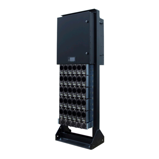
- Page 7 List of Figures Figure 1 — Front angle view of the CXPS-W system ............... 8 Figure 2 — LVD Override and Manual Battery Disconnect ............. 12 Figure 3 — 12 Position Internal Return (top of 4T and 2T) ............. 17 Figure 4 —...
-
Page 8: Safety
Keep it in a safe place. Review the drawings and illustrations contained in this manual before proceeding. If there are any questions regarding the safe installation or operation of this product, contact Alpha Technologies or the nearest Alpha representative. Save this document for future reference. -
Page 9: Electrical Safety
1.4 Electrical Safety WARNING! Hazardous voltages are present at the input of power systems. The DC output from rectifiers and batteries, though not dangerous in voltage, has a high short-circuit current capacity that may cause severe burns and electrical arcing. •... -
Page 10: Introduction
2. Introduction 2.1 Scope of the Manual This manual covers the features, options, installation and startup of Alpha Technologies CXPS-W power system. Im- ages contained in this document are for illustrative purposes only and may not exactly match your installation. -
Page 11: Specifications
3. Specifications Table A — Specifications CXPS-W Electrical Primary Output Voltage: -48V Secondary Output Voltage: +24V (optional) 6x 30A, Single Phase, 208 to 277Vac 4.0kW Rectifier Shelf AC Input: 2x 50A, 3 Phase, 208Vac (w/o neutral) 2x 30A, 3 Phase, 277/480Vac (w/ neutral) 2.4kW Rectifier Shelf AC Input: 2x 40A &... - Page 12 System: 227kg (500lbs) approx Weight: 4.0kW Rectifier: 8.5kg (19lbs) per module 2.4kW Rectifier: 1.76kg (3.9lbs) per module Environmental Operating Temperature: 0 to 40°C (32 to 104°F) Storage Temperature: Humidity: 0 to 95% RH non-condensing Elevation: 500 to 2800m (-1640 to 9186ft) Compliance CSA C22.2 No. 60950-1 CSA: UL 60950-1 The above information is valid at the time of publication. Consult factory for up-to-date ordering information. Specifications are subject to change without notice.
-
Page 13: Features
4. Features 4.1 System Overview 4.1.1 Seismic Racks The CXPS-W system can be installed in a variety of Alpha provided, 23” seismic racks. These racks have been Z4 rated and NEBS L3 certified. The racks vary in their Z4 seismic capabilities from 500. lb to 2500 .lb and in their heights from a 3.5’... -
Page 14: Figure 2 - Lvd Override And Manual Battery Disconnect
4.1.2.3 Three Tier • Accepts a maximum of three distribution tiers • Rated for a max of 1200A or 1800A • Option for a 1200A or 2000A LVBD • 14RU in height • Five battery landing positions (ten cables back to back) (return bar has one extra position for the site ground) •... - Page 15 4.1.4 24 Position Bullet Tier Features • Occupies 1 tier position • Can be installed in any location of the ‘W’ distribution cabinet • 600A tier rating (Monitored by 800A shunt) • Each tier accepts 1P (125A), 2P (200A), 3P (300A) •...
- Page 16 4.1.6 20 Position LVLD Bullet Tier Features • Occupies 1 tier position • Can be installed in any location in any of the ‘W’ distribution cabinet • 600A tier rating (Monitored by 800A shunt) • Load shedding via 600A contactor •...
- Page 17 2 Position TPL Tier Theory of Operation 800A TPL 800A TPL TPL 1 TPL 2 300A 300A (A Side) (B Side) 600A LOAD If TPL 1 (or) TPL 2 operate and open, then the other TPL will carry the entire load current and not exceed the 80% rating of the fuse and the 600A rating of the tier.
- Page 18 4.1.10 4 Position TPL Tier Features • Occupies 1 tier position • Can be installed in only the top tier in any of the ‘W’ distribution cabinet • 1200A tier rating (Monitored by 1500A shunt) • Each position accepts max 800A TPL fuse •...
-
Page 19: Figure 3 - 12 Position Internal Return (Top Of 4T And 2T)
4.1.12 12 Position High Capacity Breaker Tier Features • Occupies 2 tier positions • Can be installed only in specific location within the ‘W’ distribution cabinet Tiers 1 and 2, in a 2T distribution cabinet Tiers 1 and 2, in a 3T distribution cabinet Tiers 1 and 2 and tiers 3 and 4, in a 4T distribution cabinet •... - Page 20 4.1.14 10 Position GMT Fuse block • Mounted on the side of the distribution cabinet • 30A max rating • Can accept 15A GMT fuses NOTE: Only install a 15A fuse if the adjacent positions are empty. Otherwise install a 10A fuse maxi- mum per position.
-
Page 21: Figure 5 - Cable Lacing Bar Kit
4.1.16 Cable Lacing Bar Kit • The cable lacing bar kit is a metallic bar that can be ordered and installed on the top of the cabinet (as shown in pictures) • This bar acts as a staging point for installers to lace cables that ‘waterfall’ from the ladder rack prior to being terminated within the distribution cabinet. -
Page 22: Cordex Hp Controller (Cxc Hp)
4.2 Cordex HP Controller (CXC HP) The Cordex™ HP (CXC HP) controller provides centralized setup, control and monitoring of power systems. This ranges from simple monitoring and threshold alarms for temperature, voltage and current, to advanced battery charging and diagnostic features. The controller supports dual Ethernet ports and a 4.3”... -
Page 23: External Peripherals
• USB: dual ports on both the front and rear of the controller for upgrades and file management via a standard USB flash drive. • CAN: dual independent CAN bus ports for communication with the Alpha Cordex™ and AMPS family of products, which allows for a greater number of devices. -
Page 24: Figure 9 - 6I-Adio Power Module
4.3.1.2 Digital Inputs The L-ADIO can accommodate up to eight digital input channels, D1 – D8. Each channel responds to a zero or sys- tem voltage potential at the input to activate or deactivate the appropriate condition. These channels can monitor digital alarm/control signals from rectifiers, converters and many other types of equip- ment. -
Page 25: Cordex Hp 4.0Kw Rectifiers
4.4 Cordex HP 4.0kW Rectifiers 4.4.1 Rectifer Features • High performance 83.3A rectifier for 48V telecom applications • 95.3% efficiency for increased OPEX savings and reduced carbon footprint • High power density 4RU compact design delivering up to 24kW per 23" shelf •... - Page 26 4.4.4 4.0kW Rectifier Shelf Busing The CXPS-W system can accept from a single 4.0kW rectifier shelf up to five shelves as shown in the following pic- tures. • 1x 4.0kW Rectifier Shelf Kit • 2x 4.0kW Rectifier Shelf kit • 3x 4.0kW Rectifier Shelf kit •...
-
Page 27: Kw Rectifier Shelf
4.5 2.4kW Rectifier Shelf 4.5.1 Rectifier Features • High performance compact 50A rectifier for 48Vdc telecom application • High efficiency (96 +%) for reduced OPEX and carbon footprint • High temperature operating range for installation in non-controlled environments • Multiple configurations providing 250A or 12kW in a compact 1RU shelf •... - Page 28 4.5.4 2.4kW Rectifier Shelf Busing The CXPS-W system can accept from two 2.4kW rectifier shelves, up to five shelves. Additional rectifier shelves can be added in the field live. The 2, 3 and 4 rectifier shelf bus options are expandable in the following manner: •...
-
Page 29: Kw 48V To 24V Converter Shelf
4.6 2.0Kw 48V to 24V Converter Shelf The CXPS-W system accepts up to a maximum of one 23" module 48V to 24V converter shelf. 4.6.1 Converter Features • Supports small to medium 24Vdc loads from a 48Vdc power system • High power density modular design, 2kW output per module •... -
Page 30: Integrated Battery Trays
4.7 Integrated Battery Trays The CXPS-W system is designed to integrate battery trays below the power system. These battery trays can accept standard 12V mono-blocks ranging in height from 6RU-8RU. The battery trays are factory installed and pre-wired for ease of installation. They can be configured for with or without battery breakers as Over Current Protection Devices (OCPD). -
Page 31: Remote Return Bar Kit
4.8 Remote Return Bar Kit The external return bar kit is an alternate option for landing return connections from the loads. It serves as the com- mon connection point for the positive side of the power section and the batteries. The CXPS-W Remote Return Bar has a capacity of 2500A per kit. -
Page 32: Figure 13 - Iinterbay Busing (2000A Shown Here)
4.8.1 Interbay Busing • The interbay busing option provides the user the capability to field expand a 1200A or a 2000A CXPS-W system to a 2400A or 4000A system. • The new, higher capacity system will still maintain one centralized controller in the primary bay. •... -
Page 33: Inspection
If any damage is observed contact the carrier immediately. Continue the inspection for any internal damage. In the unlikely event of internal damage, inform the carrier and contact Alpha Technologies for advice on the impact of any damage. -
Page 34: Installation
6. Installation Only qualified personnel should install and connect the power components within the Alpha power system. For the battery installation, refer primarily to the manufacturer’s manual. Frequent reference is made to drawings located at the rear of this manual. Layout and schematic drawings are pro- vided with the power system. - Page 35 6.3.1 Installation Verify that all battery breakers, DC circuit breakers, and fuses on the distribution panels are either in the OFF position or removed. Apply a corrosion-inhibiting agent, such as NO-OX-ID “A”, on all battery terminal connections. 1. If required, assemble the battery rack and the cells or mono-blocks as per the installation instructions supplied with the batteries.
- Page 36 After assembly, number the batteries and take “as received” readings, including specific gravity, cell voltage, and temperature. Designate one cell as the pilot cell. This is usually the cell with either the lowest specific gravity or volt- age. Refer to the manufacturer's literature for guidelines. See the following table for typical maintenance report: Company: _____________________________________________________ Date: _____________________ Address: _________________________________________________________________________________ Battery location and/or number:_______________________________________________________________...
-
Page 37: Power System Assembly And Mounting
6.4 Power System Assembly and Mounting The power system must be mounted in a clean and dry environment. Sufficient free space must be provided at the front and rear of the power system. This is to meet the cooling requirements of the rectifiers and to allow easy ac- cess to the power system components. -
Page 38: Wiring
7. Wiring This chapter provides cabling details and notes on cable sizing for DC applications with respect to the product. WARNING! Ensure that the power is switched off by switching off rectifiers and removing battery line fuses, turn off battery breakers before attempting work on the wiring. Use a volt- meter to verify the absence of a voltage. -
Page 39: Grounding
Table C — Cable size equivalents (AWG to Metric) Cable size Circular mils Square millimeters Equivalent metric (see notes 1 and 2) cable 0000 AWG (or 4/0) 211600 107.2 313 MCM (or kcmil) 313600 150 or 185 350 MCM (or kcmil) 350000 177.36 373 MCM (or kcmil) -
Page 40: Ac Supply For The Rectifiers
7.2.1 Frame Ground The power plant frame must be connected to the MGB or FGB. This connection is necessary for personnel safety and to meet many telco-grounding requirements. Use #2/0 for frame ground. Remove paint in lug contact area to ensure a good electrical connection. Connection to Overhead Trays The rack upper crossbar (figure ) has three-five 5/8"... -
Page 41: Figure 18 - Can Bus Termination
7.3.2 CAN Bus Termination - 4.0kW Rectifier Shelf The CAN bus provides a communication path between the controller and rectifiers. In a single bay, the CAN bus cabling is daisy-chained from the L-ADIO, to the top rectifier shelf. The cable is then daisy-chained from the top shelf, to lower shelves, in sequence. -
Page 42: Ac Wiring 2.4Kw Rectifier Shelf
7.4 AC Wiring 2.4kW Rectifier Shelf 7.4.1 AC Feeder Protection/Sizing To maximize system reliability, each feed should have a dedicated protection feeder breaker located at the AC dis- tribution panel. The feeder breaker can also act as the disconnect device for the connected modules. Refer to the specifications at the back of this manual for Alpha breaker and wire size recommendations. -
Page 43: Figure 21 - Terminator
7.4.2 Can Bus Termination - 2.4kW Rectifier Shelf Two CAN serial ports (modular jacks with offset latches), are provided for communications with Alpha Cordex recti- fiers and other CAN-enabled equipment. These are located on the left-sed of the rectifier shelf as viewed from the front. -
Page 44: Dc Wiring
7.5 DC Wiring WARNING! Leave cables or busbars disconnected at the battery and verify the output polarity using a voltmeter. Make battery connections only after all other wiring is completed. DC output wire must be UL approved XHHW or RHH/RHW (for Canadian users, RW90 Type). Control and sense wires must be UL approved Style 1015 (for Canadian users, TEW type). -
Page 45: Figure 23 - Battery Temperature Probes
7.5.3 Connecting the External Battery Alarm These instructions apply to the following Alpha's 0912xxx-xxx series of battery bays. 1. Connect a #18AWG wire (black recommended) to the terminal block "ALARM" on the battery bay. 2. Connect to the L-ADIO; D2 (pos. 26). 3. -
Page 46: Dual Voltage Conversion
7.6 Dual Voltage Conversion The staged tier is split in four sections. It is factory configured to supply two voltages: -48 Vdc on the left section (positions 1 through 12), and +24 Vdc on the right three sections (positions 13-24). The +24 Vdc sections are joined by a link bar (see Figure 25). -
Page 47: High Capacity Breaker Alarm And Shunt Wiring
7.7 High Capacity Breaker Alarm and Shunt Wiring 1. Connect the alarm wire (-HOT) from position NC on the breaker, to one of the available digital inputs on the L-ADIO. 2. Add a (+ RETURN) jumper from the digital input. 3. -
Page 48: Signal Wiring
7.8 Signal Wiring 1. Use the Form C relay contacts on the L-ADIO to extend various alarm or control signals to an external site monitor. Figure 29 shows the L-ADIO module layout table F lists the factory default settings. 2. Use 0.129 mm² (#26 AWG) or larger wire. 3. -
Page 49: Figure 30 - Digital Input Connection Method
7.8.2 Analog Inputs WARNING! Ensure that the correct polarity is used for all input cable terminations. The analog input channels are used to monitor various types of electrical signals. Some of the analog channels are reserved for specific signals, while others are designated as general-purpose inputs, which accommodate various types of analog signals. -
Page 50: System Startup
8. System Startup After completing the system installation and power system wiring, perform the following startup and test procedure to ensure proper operation. 1. Visually inspect the installation thoroughly. 2. Verify: AC input power is off. Batteries are disconnected. All breakers are off and no fuses installed if any loads are connected. All power modules are removed from the shelves. - Page 51 8.8.1 Factory Ranges and Defaults Table H shows the rectifier settings/ranges/defaults. Changes are made through the CXC HP controller interface. Table H — Rectifier factory ranges and defaults (TBD) Setting Range (minimum to maximum) Default Float (FL) Voltage 47.5 – 58.2 V 54 V Equalize (EQ) Voltage 49.8 –...
-
Page 52: Maintenance
9. Maintenance Although very little maintenance is required with Alpha systems, routine checks and adjustments are recommended to ensure optimum system performance. Qualified service personnel should do the repairs. The following table lists a few maintenance procedures for this system. These procedures should be performed at least once a year. -
Page 53: Acronyms And Definitions
10. Acronyms and Definitions Alternating current ANSI American National Standards Institute American Wire Gauge British thermal unit Controller area network Canadian Electrical Code Canadian Standards Association Cordex™ series; e.g., CXC for Cordex System Controller Direct current DHCP Dynamic Host Configuration Protocol Electronic Industries Alliance Electromagnetic compatibility Electromagnetic interference Electromagnetic Compatibility and Radio Spectrum Matters... -
Page 54: Warranty And Service Information
11. Warranty and Service Information 11.1 Technical Support In Canada and the USA, call toll free 1-888-462-7487 Customers outside Canada and the USA, call +1-604-436-5547. 11.2 Warranty Statement For full information details review Alpha's online Warranty Statement at http://www.alpha.ca/warranty. 11.3 Limited Hardware Warranty Alpha warrants that for a period of two (2) years from the date of shipment its products shall be free from defects under normal authorized use consistent with the product specifications and Alpha’s instructions, unless otherwise specified in the product manual, in which case, the terms of the manual will take precedence... -
Page 55: Certification
12. Certification 12.6.1.1 About CSA and NRTL CSA (Canadian Standards Association also known as CSA International) was established in 1919 as an independent testing laboratory in Canada. CSA received its recognition as an NRTL (Nationally Recognized Testing Laboratory) in 1992 from OSHA (Occupational Safety and Health Administration) in the United States of America (Docket No. - Page 64 Canada and USA: 1-888-462-7487 International: +1-604-436-5547 Visit us at www.alpha.ca Due to continuing product development, Alpha Technologies reserves the right to change specifications without notice. Copyright © 2017 Alpha Technologies. All Rights Reserved. Alpha® is a registered trademark of Alpha Technologies.
Need help?
Do you have a question about the CXPS-W Series and is the answer not in the manual?
Questions and answers