
Related Manuals for Alpha Technologies Cordex


Summary of Contents for Alpha Technologies Cordex
- Page 1 Cordex PSU, 24V/400W or 48V/650W Web Enabled, DIN Rail/Wall Mount Power Supply Installation & Operation Manual Part # 0100011-J0 Effective: 09/2013 Your Power Solutions Partner member of The Group ™...
- Page 3 IMPORTANT SAFETY INSTRUCTIONS SAVE THESE INSTRUCTIONS 1. Please read this manual prior to use to become familiar with the product’s numerous features and operating procedures. To obtain a maximum degree of safety, follow the sequences as outlined. 2. This manual provides warnings and special notes for the user: a.
-
Page 5: Table Of Contents
Product Overview ............................1 Specifications ..............................2 ................................... 3 EATURES Cordex Integrated System Controller (CXCI+) ..................... 3 Analog Input Channels ..........................4 Digital Input Channels ........................... 4 Alarm and Control Output Relays ......................... 4 Network Connection and Remote Communications ..................4 Rectifiers ............................... - Page 6 MOV Replacement ............................22 ........................24 ARRANTY AND ERVICE NFORMATION Technical Support ............................24 Warranty ..............................24 Battery Warranty ............................24 Return of Material ............................24 10 A ............................. 25 CRONYMS AND EFINITIONS...
-
Page 7: Introduction
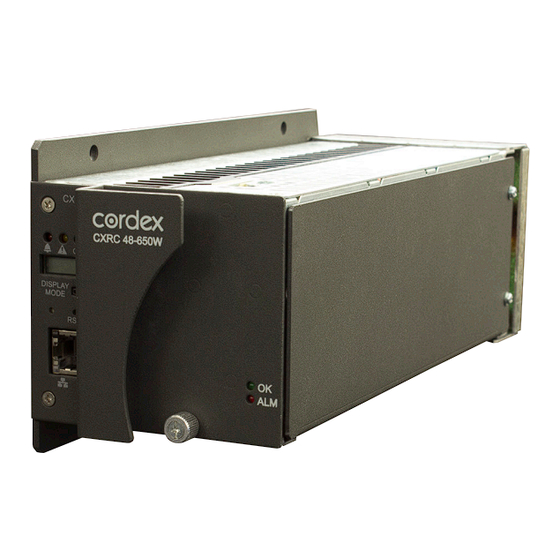
Extended temperature range for installation in harsh outdoor environments • • Wide AC input operating range for worldwide installation requirements Rectifier module CXCI+ controller (650W shown) Figure 1– Cordex PSU, 24V/400W or 48V/650W shelf system with integrated CXCI+ controller 0100011-J0 Rev D Page 1 of 25... -
Page 8: Specifications
Specifications The product is available under the following part numbers: • 24V-400W model, DIN Rail mount: #0100011-002 • 48V-650W model, DIN Rail mount: #0100012-002 Electrical >48V/650W >24V/400W Input voltage: Operating: 120/208/240Vac 120/208/240Vac Extended: Low: 90 to 120Vac (de-rated power) Input frequency: 45 to 65Hz 45 to 65Hz Current:... -
Page 9: Features
Features Alpha’s Cordex PSU is an integrated, fully-featured DC power system in a compact form factor. It is designed to provide power to critical loads while enabling remote site monitoring and delivering critical information on demand. The PSU supplies reliable and low output ripple current along with short circuit, over voltage, over temperature and over load protection. -
Page 10: Analog Input Channels
Relay K1 is mapped to the LVBD (see Section 5.9.4 on page 16). Network Connection and Remote Communications The Cordex system can be set up, monitored and tested via Ethernet 10/100 Base-T serial data connection. The communication protocol supports a web interface. -
Page 11: Rectifiers
Rectifiers Figure 3–Rectifier front panel (400W shown) 2.6.1 Front Panel LEDs The front panel LEDs provide rectifier status summary and help to locate a specific module under CXC control. The top LED (green) is on when AC is within a valid range and the rectifier is delivering power to the load. -
Page 12: True Module Fail Alarm
NOTE: For Cordex rectifier systems without batteries (or with a very light load; below 2.5% of rated output) it is recommended that the ramp test be disabled to avoid nuisance alarms. The Ramp Test feature is enabled/disabled via the CXC menu item: Rectifiers >... -
Page 13: High Voltage Shutdown (Hvsd)
AC power failure or input fuse failure. 2.16 CAN bus All alarming and control of Cordex rectifiers is communicated to/from the CXC via a CAN bus. 0100011-J0 Rev D Page 7 of 25... -
Page 14: Inspection
If the original container is unavailable, make sure the product is packed with at least three inches of shock-absorbing material to prevent shipping damage. NOTE: Alpha Technologies is not responsible for damage caused by the improper packaging of returned products. Check for Damage Prior to unpacking the product, note any damage to the shipping container. -
Page 15: Installation
Installation This chapter is provided for qualified installation personnel. NOTE: Mount in a clean and dry environment Safety Precautions WARNING Hazardous voltages are present at the input of power systems. The DC output from the rectifiers and battery system, though not dangerous in voltage, has a high short circuit current capacity that may cause severe burns and electrical arcing. - Page 16 Front view Figure 5-Panel/Wallmount Option The Cordex PSU can be mounted to surfaces such as wood (at least 3/4" thick), metal or concrete with #10 (M5) fastening hardware that is appropriate for the chosen surface. 1. Remove the 2 DIN rail mounting clips (3x screws per clip shown in Figure 4).
-
Page 17: Wiring And Connections
Wiring and Connections WARNING Hazardous AC voltages may be present. Ensure power at the AC service panel is off before attempting work on the AC connections. Use a voltmeter to verify the absence of voltage. Clearly mark the correct polarity of the battery leads before commencing work on DC connections. Tools Required Use this list as a guide: •... -
Page 18: Wiring Schematic
Wiring Schematic K2 NO LINE K2 COM K2 NC NEUTRAL K3 NO K3 COM GROUND K3 NC K4 NO K4 COM K4 NC LOAD- LOAD+ BATTERY- TIED TO COMM BATTERY+ TIED TO COMM Figure 6 – Wiring Connections Calculating Output Wire Size Requirements Wire size is calculated by first determining the appropriate maximum voltage drop requirement. -
Page 19: Network Connection And Remote Communications Via Cxci
Network Connection and Remote Communications via CXCI+ The Cordex system can be set up, monitored and tested using the CXCI+ front panel RJ-45 jack, which provides an Ethernet 10/100 Base-T serial connection to: • A user supplied network (TCP/IP secured by user) for remote access •... - Page 20 5.9.1.3 Current Current Input #1 (load current per CXC software) is wired internally to the system current shunt (75A/50mV) in the negative lead. 5.9.2 Digital Inputs for CXCI+ The digital input channels (factory-installed) are used to monitor various alarm and control signals. All input channels are voltage activated and accept a bipolar (i.e.
- Page 21 5.9.3 Alarm (Relay) Outputs CAUTION: Relay contacts are not power limited. Connect relay outputs to SELV circuits only. Terminals provide contacts for extending various alarm or control signals. Each relay output can be wired for NO or NC operation during an alarm or control condition. See Figure 8. CAUTION: Connect the common contact of the relay to the powered line.
- Page 22 5.9.4 Integrated LVBD (Battery Disconnect) Configuration Figure 9 shows options for configuring the integrated LVBD relay. Rectifier (-) Controller (-) Load (-) LVBD Bypass Pins Battery (-) LVBD Relay K1 Always connected (default) Jumper JP3 CONTROLLER BATTERY POWER SELECTION Disconnect when LVD opens Figure 9—Configuring the LVBD on the The PSU has an integrated LVBD (relay K1).
-
Page 23: Operation
Operation Main Rectifier States Rectifier operation can be broken up into five main states: 1. Off, 2. Start delay, 3. Soft start, 4. Normal operation, 5. Turning off. Each state is characterized as being distinct and necessary for the operation of the rectifier. These states are briefly described below. -
Page 24: Main Rectifier Modes
Main Rectifier Modes In addition to Main Rectifier States, there is a set of Main Rectifier Modes. These modes can be divided into two categories as follows: 6.2.1 Output Voltage Modes Voltage modes can be thought of as modes that, under software control, can directly adjust the output voltage. The qualification of ‘under software control’... -
Page 25: 400W Rectifier Factory Ranges And Defaults
Enable NOTE: OVP cannot be set below the present system/FL/EQ/BT voltage setting or the safe mode voltage (default) of 25.7V. Table F–Cordex 24-400W factory ranges and defaults 650W Rectifier Factory Ranges and Defaults The following table lists the rectifier settings/ranges/defaults; changes are made via the CXC:... -
Page 26: System Startup
System Startup After completing the shelf wiring and installation, perform the following startup and test procedure to ensure proper operation: 1. Check system connections. • Ensure AC is off, battery is disconnected, • Check the polarity of all connections. 2. Verify AC and Power the Shelf •... - Page 27 This reset allows local access; for example, with a laptop and a standard network crossover cable. See the current version software manual for details. 7.1.3 Hard Reset The hard reset button is the unmarked button on the front panel (see Figure 2). This reset button can be used to restart the microprocessor if the soft reset button fails to operate as described in section 7.1.1.
-
Page 28: Maintenance
Maintenance Although very little maintenance is required with Alpha systems, routine checks and adjustments are recommended to ensure optimum system performance. Qualified service personnel should do repairs. The following table lists a few maintenance procedures for this system. These procedures should be performed at least once a year. - Page 29 4. Locate the “MOV pack.” Remove the three (3) screws securing the MOVs and remove. 5. Decontaminate the affected area with flux remover or a similar cleaning compound. This is to remove any metallic particles or carbon, which may have been deposited when the MOV failed. 6.
-
Page 30: Warranty And Service Information
Warranty Alpha Technologies Ltd. warrants all equipment manufactured by it to be free from defects in parts and labor, for a period of two years from the date of shipment from the factory. The warranty provides for repairing, replacing or issuing credit (at Alpha’s discretion) for any equipment manufactured by it and returned by the customer to the... -
Page 31: Acronyms And Definitions
American wire gauge British thermal unit Controller area network Canadian Electrical Code Canadian Standards Association Cordex™ series; e.g., CXC for Cordex System Controller Direct current DHCP Dynamic host configuration protocol Electromagnetic compatibility Electromagnetic interference Electromagnetic compatibility and radio spectrum matters... - Page 32 Consult the dealer or an experienced radio/TV technician for help. Alpha Technologies Ltd. 7400233-S0 Rev B Printed in Canada. © 2013 Alpha Technologies Ltd. ALPHA and CORDEX are trademarks of Alpha Technologies Ltd. All Rights Reserved. Page 1 of 3...
- Page 33 Ethernet RJ-45, Alpha Modem DB-9, CAN [see shelf specifications] CXCI+ Communication Ports: Ethernet RJ-45, CAN [see shelf specifications] Alpha Technologies Ltd. 7400233-S0 Rev B Printed in Canada. © 2011 Alpha Technologies Ltd. ALPHA and CORDEX are trademarks of Alpha Technologies Ltd. All Rights Reserved. Page 2 of 3...
- Page 34 The above information is valid at the time of publication. Consult factory for up-to-date ordering information. Specifications are subject to change without notice. Alpha Technologies Ltd. 7400233-S0 Rev B Printed in Canada. © 2011 Alpha Technologies Ltd. ALPHA and CORDEX are trademarks of Alpha Technologies Ltd. All Rights Reserved. Page 3 of 3...
- Page 36 Canada and USA: 1-888-462-7487 International: +1-604-436-5547 Visit us at www.alpha.ca Due to continuing product development, Alpha Technologies reserves the right to change specifications without notice. Copyright © 2013 Alpha Technologies. All Rights Reserved. Alpha® is a registered trademark of Alpha Technologies.
Need help?
Do you have a question about the Cordex and is the answer not in the manual?
Questions and answers