Table of Contents
Advertisement
Quick Links
Advertisement
Table of Contents

Related Manuals for SPL Track One 2960


Summary of Contents for SPL Track One 2960
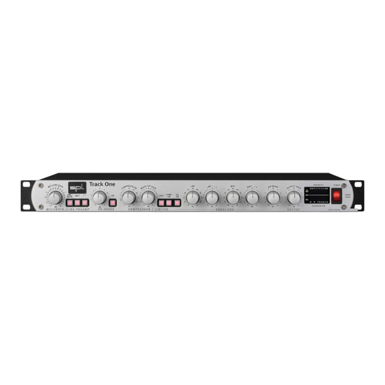
- Page 1 Manual Track One Model 2960 Channel Strip...
- Page 2 This document is the property of SPL and may not be copied or reproduced in any manner, in part or fully, without prior authorization by SPL.
-
Page 3: Table Of Contents
CONTROL ELEMENTS Preamplifer MIC/LINE GAIN, 48 V, Activating phantom power, High pass, Gain adjustments ....11 De-Esser EQ ON, De-Esser control, SPL De-Esser technology ............12 Compressor/Limiter COMP. ON, LIMIT, COMPRESSION ................... 13 MAKE UP GAIN, SPL compressor technology ..............14 Equalizer ON, LMF, LMF -/+, MHF .................... -
Page 4: Symbols & Notes, Scope Of Delivery & Packaging, Important Security Information
The symbol of a lamp directs your attention to explanations of important functions or applica- tions. Attention: Do not attempt any alterations to this machine without the approval or supervision of SPL electronics GmbH. Doing so could nullify completely any and all of your warranty/guar- antee rights and claims to user support. Scope of Delivery & Packaging The scope of delivery comprises the Track One, the external power supply, the guarantee card and this manual. -
Page 5: Hoop Up
Important Security Information Lightning: Before thunderstorms or other severe weather, disconnect the machine from wall power (but to avoid life threatening lightning strikes, not during a storm). Similarly, before any severe weather, disconnect all the power connections of other machines and antenna and phone/network cables which may be interconnected so that no lightning damage or overload results from such secondary connections. -
Page 6: Introduction, Principles
Introduction SPL is well-known for the development of highly specialized audio-tools. Our philosophy, “one product for one task”, is aimed at fast and simple operation in conjunction with high processing quality to ensure an excellent musical performance. With the Track One we have produced a complete channel strip which for the greater part is based on the processing concepts already successfully realized in other products. -
Page 7: Rear Panel
Rear Panel Wiring diagramm Track One... -
Page 8: Sockets & Switches
Rear Panel Sockets and switches Signal connection Switch off the unit before you begin the process of making the first or any subsequent connec- tions. Neglecting this can damage either or both your ears and your equipment. 1/4" TRS/TS sockets The INSTR./LINE IN socket only supports unbalanced connections (1/4" TS/mono jack connector). All other sockets are support both balanced (1/4" TRS/stereo jack connector) and unbalanced connections (1/4" TS/mono jack connector). XLR sockets All XLR sockets are balanced inputs or outputs. Input sockets are always female for plugging in male connectors, output sockets are always male for female connectors. - Page 9 Rear Panel Sockets and switches VOLTAGE VOLTAGE | FUSE 230 V ~50Hz The rear panel VOLTAGE selector sets the local line voltage (115 V position: 110-120 volts/6o Hz, Fuse: 315 mA 230 V position: 220-240 volts/50 Hz). The diagram to the right shows the correct switch posi- tion for 230 V power supply.
- Page 10 Rear Panel Sockets and switches ANALOG OUTPUTS The ANALOG OUTPUTS deliver balanced output signals. An output trans former can be equipped optionally (see page 29). Since both connectors are working in parallel, unbalancing one connector also unbalances the other one. If for example a mono jack connector is plugged into to the jack socket, the XLR socket is operating unbalanced as well.
-
Page 11: Control Elements
Control Elements Preamplifier MIC/LINE GAIN, LINE/INSTR. The MIC/LINE GAIN control determines the level of preamplification for microphone and line or instrument signals. In standard mode you control microphone preamplification. Engage the LINE/INSTR. switch to control line or instrument signals. The preamplification values for microphone signals cover a range from +8 dB up to + 63 dB. If the optional microphone input transformer is installed, the scaled values are to be increased by ca. -
Page 12: De-Esser
As a result, the SPL De-Esser does not need to be monitored and re-adjusted permanently to keep processing constant – and it can always be applied before the compressor, as changing its position would not be an advantage. -
Page 13: Compressor/Limiter
Control Elements Compressor/Limiter COMP. ON The COMP. ON button activates the compressor module. At the same time the GAIN REDUCTION display shows the processing intensity (also see “MAKE UP GAIN” on page 14 and “GAIN REDUCTION” on page 17). LIMIT The LIMIT switch turns the compressor into a limiter. The COMPRESSION control now serves the purpose of controlling the threshold. -
Page 14: Make Up Gain, Spl Compressor Technology
A further technical specialty of the circuitry contributes to the high audio quality of the compressor in the Track One: SPL’s double VCA drive. One VCA receives the in-phase, the other the out-of-phase signal. Subsequently the signal is passed through a differential ampli- fier. -
Page 15: Equalizer On, Lmf, Lmf -/+, Mhf
Control Elements Equalizer EQ ON The ON button inserts the equalizer module into the signal path. The input signal comes from the compressor. Tip: Deactivating the equalizer module at the beginning of a recording can avoid irritations. Otherwise and especially with intensive EQ settings tonal changes could occur immediately. The center frequency of the half-parametric bass filter is set with the LMF control (low/mid frequencies). -
Page 16: Mhf -/+, Recommendation On Frequency Settings For Lmf And Mhf, Air Band
Control Elements Equalizer MHF -/+ This control determines the boost, or cut of the MHF filter; the maximum values lie between +/- 12 dB. The MHF filter utilizes the proportional-Q-principle, too: the higher the boost or cut values are set, so the bandwidth becomes narrower; by low boost or cut values the bandwidth increases (the exact curves of the MHF filter can be seen in diagram 3 on page 21). -
Page 17: Display Area
Control Elements Display area All status and level displays are concentrated in a central display area, so all important infor- mation can be perceived at a glance. S-DET. The S-DETECT LED shows when sibilants have been detected. It is only active when the de-esser is switched on, but it is independent from the de-esser control. -
Page 19: Power Supply
Power Supply Built around a toroidal transformer, the power supply ensures a minimal electromagnetic field with no hum or mechanical noise. The power supply‘s output side is filtered by an RC circuit to extract noise and hums caused by your power service. 6000 µf capacitors smooth out the positive and negative half waves. -
Page 20: Measurements
Measurements Compressor/Limiter, LMF Diagram 1: compressor curves Line A displays the ratio between input and output Line B shows the curve character- istics of the compressor Line C protrays the limiter‘s curve characteristics Diagram 2: various LMF settings around 200 Hz Track One... - Page 21 Measurements MHF, Air Band Diagram 3: various cut and boost settings of the MHF filter at around 1,8 kHz Diagram 4: various cut and boost settings of the Air Band filter Track One...
-
Page 22: Options: A/D Converter, I/O Transformers
Please note that you can order products with optional equipment from all dealers, even if they do only list standard product versions, for example in an online store. Please contact your dealer or SPL before you place an order. Optional equipment can also be installed after sales. Available option for the Track One, model 2960: •...
Need help?
Do you have a question about the Track One 2960 and is the answer not in the manual?
Questions and answers