Table of Contents
Advertisement
E2003 Lennox Industries Inc.
Dallas, Texas, USA
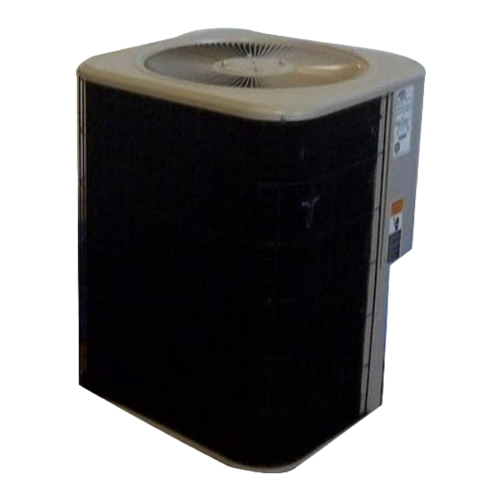
10HPB Outdoor Units
®
Lennox Merit
Series 10HPB outdoor units are approved
and warranted only for installation with specially matched
indoor coils, line sets, and refrigerant control systems as
designated by Lennox. Refer to Lennox Engineering
Handbook for expansion valve kits which must be ordered
separately.
Shipping and Packing List
1 − Assembled 10HPB outdoor unit
1 − Coupling (18, 24 and 30)
Check unit for shipping damage. Consult last carrier imme-
diately if damage is found.
WARNING
Improper installation, adjustment, alteration, service
or maintenance can cause property damage, person-
al injury or loss of life. Installation and service must
be performed by a qualified installer or service
agency.
IMPORTANT
The Clean Air Act of 1990 bans the intentional vent-
ing of refrigerant (CFC's and HCFC's) as of July 1,
1992. Approved methods of recovery, recycling or
reclaiming must be followed. Fines and/or incarcera-
tion may be levied for noncompliance.
06/04
*2P0604*
®
Page 1
INSTALLATION
INSTRUCTIONS
10HPB Series Units
HEAT PUMP UNITS
1−1/2 through 5 tons
504,828M
06/04
Supersedes 02/04
Table of Contents
. . . . . . . . . . . . . . . . . . . . . . . . . . .
. . . . . . . . . . . . . . . . . . . . . . . . .
. . . . . . . . . . . . . . . . . . . . . . . . . . . .
. . . . . . . . . . . . . . . . . . . . . . . . . . . . . . .
. . . . . . . . . . . . . . . . . . . . . . . . . . . . . . . .
. . . . . . . . . . . . . . . . . . . . . . . . . . . . . . . . . . . . . .
. . . . . . . . . . . . . . . . . . . . . . . . . . . . . .
. . . . . . . . . . . . . . . . . . . . . . . . . . .
. . . . . . . . . . . . . . . . . . . . . . . . . . . . . . . .
. . . . . . . . . . . . . . . . . . . . . . . . . . . . . . . . . .
. . . . . . . . . . . . . . . . . . . . . . . . . . . . . . . . . . .
. . . . . . . . . . . . . . . . . . . . . . . . . . . . . . . . . . . . . .
. . . . . . . . . . . . . . . . . . . . . . . . . . . . . . . . . . . . .
. . . . . . . . . . . . . . . . . . . . . . . . . . . . .
. . . . . . . . . . . . . . . . . . . . . . . . . . . . . . .
. . . . . . . . . . . . . . . . . . . . . . . . . . . . . . . . . .
. . . . . . . . . . . . . . . . . . . . . . . . . .
RETAIN THESE INSTRUCTIONS
FOR FUTURE REFERENCE
General Information
These instructions are intended as a general guide and do
not supersede national or local codes in any way. Authori-
ties having jurisdiction should be consulted before instal-
lation.
WARNING
This product and/or the indoor unit it is matched with
may contain fiberglass wool.
Disturbing the insulation during installation, mainte-
nance, or repair will expose you to fiberglass wool
dust. Breathing this may cause lung cancer. (Fiber-
glass wool is known to the State of California to
cause cancer.)
Fiberglass wool may also cause respiratory, skin,
and eye irritation.
To reduce exposure to this substance or for further
information, consult material safety data sheets
available from address shown below, or contact your
supervisor.
Lennox Industries Inc.
P.O. Box 799900
Dallas, TX 75379−9900
Litho U.S.A.
. . . . . . . . . . . . . . . . . . . .
. . . . . . . . . . . .
504,828M
*P504828M*
1
1
1
2
3
4
6
10
10
11
12
13
13
14
16
16
18
18
18
Advertisement
Table of Contents

Subscribe to Our Youtube Channel
Related Manuals for Lennox Merit 10HPB Series


Summary of Contents for Lennox Merit 10HPB Series
-
Page 1: Table Of Contents
RETAIN THESE INSTRUCTIONS indoor coils, line sets, and refrigerant control systems as FOR FUTURE REFERENCE designated by Lennox. Refer to Lennox Engineering Handbook for expansion valve kits which must be ordered General Information separately. -
Page 2: Unit Dimensions
10HPB Unit Dimensions − inches (mm) 4-3/8 4-3/8 (111) (111) inlet 4-3/8 4-3/8 (111) (111) optional unit inlet inlet stand-off kit (4) COMPRESSOR (field−installed) coil drain outlets (around perimeter of base) 6-3/8 4-3/8 vapor line (162) (111) connection liquid line 4-3/8 6-3/8 inlet... -
Page 3: Setting The Unit
3 − In heavy snow areas, do not locate the unit where drift- Setting the Unit ing will occur. The unit base should be elevated above the depth of average snows. CAUTION NOTE − Elevation of the unit may be accomplished by constructing a frame using suitable materials. -
Page 4: Electrical
If unit coil cannot be mounted away from prevailing winter 1 − Install line voltage power supply to unit from a properly winds, a wind barrier should be constructed. Size barrier at sized disconnect switch. least the same height and width as outdoor unit. Install bar- 2 −... - Page 5 Typical Wiring Field Wiring Diagram *May be optional Figure 4 10HPB and Blower Unit 10HPB and Blower Unit Thermostat Designations Thermostat Designations (with auxiliary heat) (Some connections may not apply. (Some connections may not apply. Refer to specific thermostat and indoor unit.) Refer to specific thermostat and indoor unit.) Outdoor Outdoor...
-
Page 6: Refrigerant Piping
(sweat connections) to the indoor coil Installing Refrigerant Line (flare or sweat connections). Use Lennox L15 (sweat, non- flare) series line sets as shown in table 1 or use field-fabri- During the installation of any heat pump or a/c system, it is cated refrigerant lines. - Page 7 Installing Vertical Runs of Refrigerant Piping (new construction shown) NOTE - Similar installation practices should be used if line set is to be installed on exterior of outside wall. IMPORTANT - Refrigerant Outside Wall Vapor Line Liquid Line lines must not contact wall. Wood Block Between Studs Wire Tie...
- Page 8 Installing Horizontal Runs of Refrigerant Piping To hang line set from joist or rafter, use either metal strapping material Wire Tie or anchored heavy nylon wire ties. (around vapor line only) 8 feet Floor Joist or Roof Rafter Tape or Wire Tie 8 feet Strapping Material (around vapor line only) Metal Sleeve...
- Page 9 Transitioning from Vertical to Horizontal Runs of Refrigerant Piping Automotive Anchored Heavy Muffler-Type Nylon Wire Tie Hanger Wall Wall Stud Stud Strap Liquid Line Strap Liquid Line To Vapor Line To Vapor Line Liquid Line Vapor Line Metal Vapor Line Wrapped in Metal Sleeve...
-
Page 10: Refrigerant Metering Device
TXV match-ups and application information. Check expansion valves equipped with either Chatleff or Figure 11 flare−type fittings are available from Lennox. Refer to the Engineering Handbook for applicable expansion valves Manifold Gauge Set for use with specific match-ups. See table 2 for applicable check expansion valve kits. -
Page 11: Service Valves
10HPB Manifold Gauge Connections (Cooling Cycle) Outdoor Unit defrost thermostat distributor expansion/ reversing valve check valve biflow filter / drier outdoor coil high Indoor Unit pressure pressure muffler gauge manifold vapor vapor service line port liquid line valve HCFC−22 service drum compressor port... -
Page 12: Leak Testing
The ball valve is equipped with a service port with a factory− Leak Testing installed Schrader valve. A service port cap protects the After the line set has been connected to the indoor and Schrader valve from contamination and assures a leak− outdoor units, check the line set connections and indoor free seal. -
Page 13: Evacuation
5 − Connect the manifold gauge set high pressure hose to der with pressure regulator set to 150 psig (1034 kPa) the vapor valve service port. (Normally, the high pres- and purge the hose. Open the manifold gauge valves to break the vacuum in the line set and indoor unit. sure hose is connected to the liquid line port;... -
Page 14: Charging
6 − Set the thermostat for a cooling demand, turn on power Weighing in the Charge TXV Systems – to indoor blower unit and close the outdoor unit discon- Outdoor Temp < 65_F (18_C) nect to start the unit. If the system is void of refrigerant, or if the outdoor ambient 7 −... - Page 15 5 − Compare the subcooling value with those in table 5. If is for use on expansion valve systems only. For best results, indoor temperature should be 70°F (21°C) to 80°F (26°C). subcooling is greater than shown, recover some refrig- Monitor system pressures while charging.
-
Page 16: System Operation
Approach Method Emergency Heat Function 4 − Use the same digital thermometer used to check out- An emergency heat function is designed into some room ther- door ambient temperature to check liquid line tempera- mostats. This feature is applicable when isolation of the out- ture. - Page 17 mode and the defrost thermostat is closed or jump- control will lock out the unit if the optional high pressure switch opens. The diagnostic LEDs will display a pattern for ered. If the jumper is in the TEST position at power-up, the an open high pressure switch.
-
Page 18: Maintenance
2 − Check connecting lines, joints and coil for evidence of Maintenance oil leaks. 3 − Check condensate line and clean if necessary. WARNING Indoor Unit 1 − Clean or change filters. Electric shock hazard. Can cause inju- 2 − Adjust blower speed for cooling. Measure the pressure ry or death.
Need help?
Do you have a question about the Merit 10HPB Series and is the answer not in the manual?
Questions and answers