Advertisement
Quick Links
Installation Instructions
Series LFTWHG2
Tankless Water Heater
Sizes:
⁄
" Service Valve Set
3
4
WA R N IN G
!
Read this Manual BEFORE using this equipment.
Failure to read and follow all safety and use information
can result in death, serious personal injury, property
damage, or damage to the equipment.
Keep this Manual for future reference.
STOP!
Before connecting any components, be sure to read all
of the tankless water heater manufacturer's installation
instructions. Failure to follow instructions below can re-
sult in serious injury, death and/or property damage.
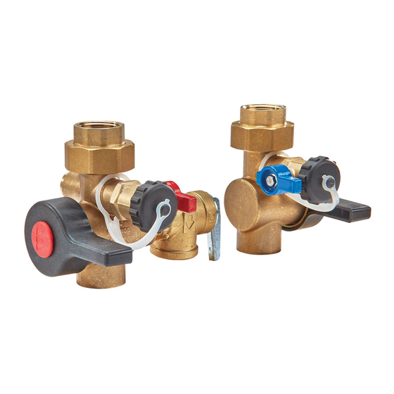
1. Identify all components and
orientations before beginning
installation
1. HOT WATER SERVICE VALVE (Fig.1)
Identified by the red handle insert.
2. COLD WATER SERVICE VALVE (Fig.2)
Identified by the blue handle insert.
3. PRESSURE RELIEF VALVE (Fig.3)
Identified by a silver test lever.
Note: ANSI Z21.22 and local codes
govern the installation of pressure
relief valves.
2. Before attaching any components
to the tankless water heater,
attach PRESSURE RELIEF VALVE
to HOT WATER ISOLATION
VALVE (Figure 4)
CAUTION
!
Do not over tighten
relief valve. Do not tighten more
than one full turn past hand tight.
a. Apply thread sealant to the exposed
threads of the pressure relief valve.
b. Thread the pressure relief valve into
the
⁄
" port on the side of the hot
3
4
water valve and hand tighten. Using
a wrench, tighten the pressure relief
valve until the discharge on the pres-
sure relief valve is positioned down-
ward on the isolation valve, as shown
in Figure 4.
3. Install COLD WATER SERVICE VALVE onto cold water
inlet of tankless water heater
a. Locate the cold water threaded inlet on the tankless water
heater and apply thread sealant to the threads.
b. Slightly loosen the union nut on the top of the cold water
valve so that the union tailpiece rotates freely.
c. Holding the cold water valve beneath the cold water inlet,
thread the union tailpiece onto the inlet and hand tighten.
Attach this end to
Using a wrench, tighten the union tailpiece. Next, position
tankless water heater
the cold water valve with the purge port pointing forward,
Fig.1
towards the front of the water heater, and hand tighten the
union nut.
d. Tighten the union nut with a wrench, making sure that the
valve does not rotate out of position.
4. Install HOT WATER SERVICE VALVE onto hot water
outlet of tankless water heater
!
Attach this end to
between the tankless water heater and pressure relief
tankless water heater
valve. (See direction arrow in Fig. 5.)
Fig.2
a. Locate the hot water threaded outlet on the tankless water
heater and apply thread sealant to the threads.
b. Slightly loosen the union nut on the top of the hot water
valve so that the union tailpiece rotates freely.
c. Holding the hot water valve beneath the hot water outlet,
thread the union tailpiece onto the outlet and hand tighten.
Using a wrench, tighten the union tailpiece. Next, position
Fig.3
the hot valve with the purge port and pressure relief valve
pointing forward, towards the front of the water heater, and
hand tighten the union nut. Tighten the union nut with a
wrench, making sure that the valve does not rotate out of
position.
Fig.4
ATTENTION INSTALLER: After installation, please leave
this Instruction Sheet for occupant's information.
IMPORTANT: Inquire with governing authorities for local
installation requirements.
!
For valves with CPVC or PEX end connections do not exceed the
tubing manufacturers pressure and temperature ratings. Refer to the
tubing manufacturers product specifications for that information.
Drain Line
TWHG2
WARNING
There should not be a shutoff located
WARNING
IS-LFTWHG2-FT/FS
Advertisement

Related Manuals for Watts LFTWHG2 Series


Summary of Contents for Watts LFTWHG2 Series
- Page 1 IS-LFTWHG2-FT/FS Installation Instructions Series LFTWHG2 Tankless Water Heater Sizes: ⁄ " Service Valve Set WA R N IN G Read this Manual BEFORE using this equipment. Failure to read and follow all safety and use information can result in death, serious personal injury, property damage, or damage to the equipment.
- Page 2 Hot Service Valve Purge Port Flow Data b. For water heater start-up, refer to the water heater owners’ manual. c. During normal operation, the main water valves are open when the main valve handle is parallel with the main valve body and closed when the main valve handle is perpendicu- lar to the main valve body.
- Page 3 9. Modular Installations When used in modular installations, the LFTWHG2 hot valve assembly can be field configured to provide hydraulic isolation of units that need service or repair while other units remain operat- ing. To provide hydraulic isolation from a pressurized hot water main, the pressure-activated seal must be rotated 180 degrees from the bottom port to the upper port as follows;...
- Page 4 Limited Warranty: Watts (the “Company”) warrants each product to be free from defects in material and workmanship under normal usage for a period of one year from the date of original shipment. In the event of such defects within the warranty period, the Company will, at its option, replace or recondition the product without charge.
Need help?
Do you have a question about the LFTWHG2 Series and is the answer not in the manual?
Questions and answers