Advertisement
Quick Links
Installation, Operation and Maintenance
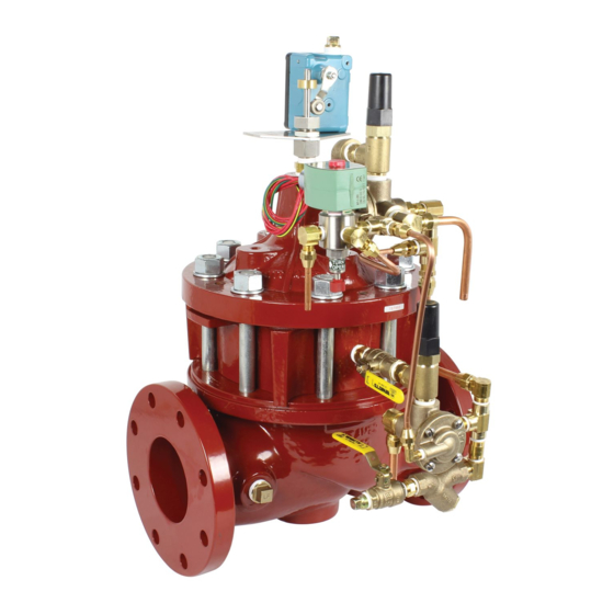
Model LFM513-6 / LFM6513-6
Deep Well Pump Control Valve
Sizes: 2" to 24"
WARNING
!
Read this Manual BEFORE using this equipment.
Failure to read and follow all safety and use information
can result in death, serious personal injury, property
damage, or damage to the equipment.
Keep this Manual for future reference.
WARNING
!
Local building or plumbing codes may require modifica-
tions to the information provided. You are required to
consult the local building and plumbing codes prior
to installation. If the information provided here is not
consistent with local building or plumbing codes, the
local codes should be followed. This product must be
installed by a licensed contractor in accordance with
local codes and ordinances.
WARNING
!
Need for Periodic Inspection/Maintenance: This product
must be tested periodically in compliance with local codes,
but at least once per year or more as service conditions
warrant . All products must be retested once maintenance
has been performed . Corrosive water conditions and/or
unauthorized adjustments or repair could render the product
ineffective for the service intended . Regular checking and
cleaning of the product's internal and external components
helps assure maximum life and proper product function .
NOTICE
For Australia and New Zealand: Pipeline strainers should be
installed between the upstream shutoff valve and the inlet of
the backflow preventer.
It's important that this device be tested periodically in compli-
ance with local codes, but at least once per year or more as
service conditions warrant. If installed on a fire sprinkler system,
all mechanical checks, such as alarm checks and backflow
preventers, should be flow tested and inspected internally in
accordance with NFPA 13 and NFPA 25.
Table of Contents
Introduction . . . . . . . . . . . . . . . . . . . . . . . . . . . . . . . . . . . . . . . . . . . . 2
Installation . . . . . . . . . . . . . . . . . . . . . . . . . . . . . . . . . . . . . . . . . . . . 2
Commissioning the Deep Well Pump Control . . . . . . . . . . . . . . . . . 3
Maintenance Schedule . . . . . . . . . . . . . . . . . . . . . . . . . . . . . . . . . . . 6
Trouble Shooting Guide . . . . . . . . . . . . . . . . . . . . . . . . . . . . . . . . . . 6
Valve Disassembly Instructions . . . . . . . . . . . . . . . . . . . . . . . . 8
ACV Schematic . . . . . . . . . . . . . . . . . . . . . . . . . . . . . . . . . . . . . . . 11
IOM-ACV-513-6_6513-6
FLOW
CLOSES VALVE
OPENS VALVE
Page
Advertisement

Subscribe to Our Youtube Channel
Related Manuals for Watts LFM513-6


Summary of Contents for Watts LFM513-6
- Page 1 IOM-ACV-513-6_6513-6 Installation, Operation and Maintenance Model LFM513-6 / LFM6513-6 Deep Well Pump Control Valve Sizes: 2" to 24" WARNING Read this Manual BEFORE using this equipment. Failure to read and follow all safety and use information can result in death, serious personal injury, property damage, or damage to the equipment.
- Page 2 LFM513-6 (Globe) Deep Well Pump Control Valve Standard Components 1 – Main Valve (M518 – Dual Chamber) 2 – Limit Switch 3 – 4-Way Solenoid 2(L) 4 – Adjustable Opening Speed 5 – Adjustable Closing Speed Y – Y-Strainer (Supply Pressure) X –...
- Page 3 STEP 3 De-energize the solenoid prior to initial pump start. STEP 4 Energize the solenoid at pump start to close the main valve, checking that the main valve closes. Figure 1 4-Way Solenoid IOM-ACV-513-6_6513-6 2115 EDP# 1917101 © 2021 Watts...
- Page 4 At valve full open position deep well pump will stop. Adjust limit switch collar to final position to ensure positive actuation of limit switch electrical contact, if necessary, by sliding up/down to loca- tion (See Figure 3). Figure 3 Limit Switch in Open Position IOM-ACV-513-6_6513-6 2115 EDP# 1917101 © 2021 Watts...
- Page 5 Automatic Control Valve Maintenance Schedule To ensure peak performance and longevity of your automatic • Annual Maintenance control valve, Watts/Ames recommends following the below – Conduct monthly & quarterly inspections. standard maintenance schedule. – Inspect & clean all strainers. • Monthly Maintenance –...
- Page 6 Check voltage at the solenoid Should be performed by actuate connection, insuring that it has licensed electrician the minimum of 85% of the coils rated voltage. Manual operated is engaged Turn manual operator counter- clockwise to disengage IOM-ACV-513-6_6513-6 2115 EDP# 1917101 © 2021 Watts...
- Page 7 5. Before removing Stem Nut, examine stem threads for mineral build-up. Remove deposits with a fine wire brush. Extreme care should be taken not to damage the finish on stem guiding surfaces when disassembling. Avoid applying pipe wrenches to top or bottom stem guide surfaces. IOM-ACV-513-6_6513-6 2115 EDP# 1917101 © 2021 Watts...
- Page 8 Mineral Dissolving Solution. Inspect parts for wear and replace if necessary. 7. Inspect valve seat. If seat is not damaged, removal is not necessary. If it is damaged please contact factory for instructions. IOM-ACV-513-6_6513-6 2115 EDP# 1917101 © 2021 Watts...
- Page 9 11. Test the integrity of the Seat Seal by following the Seat Seal Test procedure in previous section. Return valve to service by following instructions on the Technical Bulletin matching the valve function. IOM-ACV-513-6_6513-6 2115 EDP# 1917101 © 2021 Watts...
- Page 10 ACV Assembly Diagram – Series LFM513-6 NOTICE Installation: If unit is installed in any orientation other than horizontal (cover up) OR extreme space constraints exist, consult customer service prior to or at the time of order. ITEM DESCRIPTION MATERIAL Pipe Plug...
- Page 11 NOTES IOM-ACV-513-6_6513-6 2115 EDP# 1917101 © 2021 Watts...
- Page 12 Limited Warranty: Watts Regulator Co. (the “Company”) warrants each product to be free from defects in material and workmanship under normal usage for a period of one year from the date of original shipment. In the event of such defects within the warranty period, the Company will, at its option, replace or recondition the product without charge.
Need help?
Do you have a question about the LFM513-6 and is the answer not in the manual?
Questions and answers