Advertisement
Table of Contents
- 1 Installation Guidelines
- 2 Servicing the Relief Valve
- 3 Troubleshooting
- 4 Servicing the First and Second Check Valves
- 5 Add-On and Retrofit Sensor Connection Kits for Building Management Systems
- 6 Add-On and Retrofit Sensor Connection Kits for Cellular Communication
- 7 Limited Warranty
- Download this manual
Installation, Maintenance, and Repair Manual
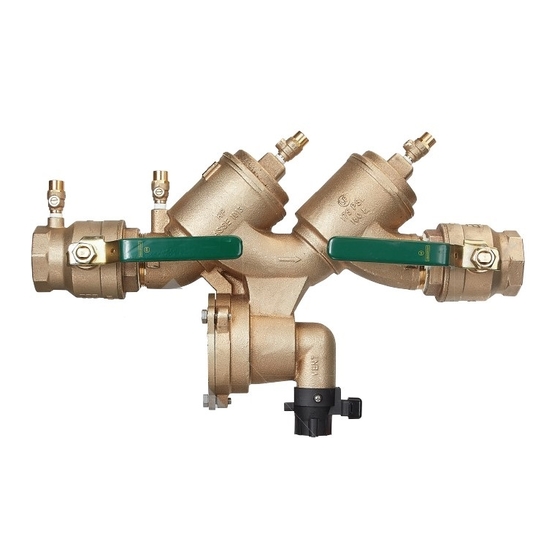
Series LF919-FS
Reduced Pressure Zone Assembly
⁄
" – 2"
1
2
WARNING
!
Read this Manual BEFORE using this equipment.
Failure to read and follow all safety and use information
can result in death, serious personal injury, property
damage, or damage to the equipment.
Keep this Manual for future reference.
WARNING
!
Local building or plumbing codes may require modifications
Local building or plumbing codes may require modifications
Local building or plumbing codes may require modifications
to the information provided. You are required to consult the
to the information provided. You are required to consult the
to the information provided. You are required to consult the
local building and plumbing codes prior to installation. If
local building and plumbing codes prior to installation. If
local building and plumbing codes prior to installation. If
the information provided here is not consistent with local
the information provided here is not consistent with local
the information provided here is not consistent with local
building or plumbing codes, the local codes should be
building or plumbing codes, the local codes should be
building or plumbing codes, the local codes should be
followed. This product must be installed by a licensed
followed. This product must be installed by a licensed
followed. This product must be installed by a licensed
contractor in accordance with local codes and ordinances.
contractor in accordance with local codes and ordinances.
contractor in accordance with local codes and ordinances.
!
WARNING
Need for Periodic Inspection/Maintenance: This prod-
Need for Periodic Inspection/Maintenance:
Need for Periodic Inspection/Maintenance:
uct must be tested periodically in compliance with local
uct must be tested periodically in compliance with local
uct must be tested periodically in compliance with local
codes, but at least once per year or more as service condi-
codes, but at least once per year or more as service condi-
codes, but at least once per year or more as service condi-
tions warrant. All products must be retested once mainte-
tions warrant. All products must be retested once mainte-
tions warrant. All products must be retested once mainte-
nance has been performed. Corrosive water conditions and/
nance has been performed. Corrosive water conditions and/
nance has been performed. Corrosive water conditions and/
or unauthorized adjustments or repair could render the prod-
or unauthorized adjustments or repair could render the prod-
or unauthorized adjustments or repair could render the prod-
uct ineffective for the service intended. Regular checking and
uct ineffective for the service intended. Regular checking and
uct ineffective for the service intended. Regular checking and
cleaning of the product's internal and external components
cleaning of the product's internal and external components
cleaning of the product's internal and external components
helps assure maximum life and proper product function.
helps assure maximum life and proper product function.
helps assure maximum life and proper product function.
NOTICE
For Australia and New Zealand, line strainers should be
For Australia and New Zealand, line strainers should be
For Australia and New Zealand, line strainers should be
installed between the upstream shutoff valve and the inlet of
installed between the upstream shutoff valve and the inlet of
installed between the upstream shutoff valve and the inlet of
the backflow preventer.
the backflow preventer.
the backflow preventer.
If installed on a fire sprinkler system, all mechanical checks,
If installed on a fire sprinkler system, all mechanical checks,
If installed on a fire sprinkler system, all mechanical checks,
such as alarm checks and backflow preventers, should be flow
such as alarm checks and backflow preventers, should be flow
such as alarm checks and backflow preventers, should be flow
tested and inspected internally in accordance with NFPA 13
and NFPA 25.
Testing
For field testing procedure, refer to Watts installation sheets
IS-TK-DL, IS-TK-7, IS-TK-9A, IS-TK-99D, and IS-TK-99E at
www.watts.com.
For other repair kits and service parts, refer to the Backflow
Prevention Products Repair Kits & Service Parts price list
PL-RP-BPD at www.watts.com.
For technical assistance contact your local Watts representative.
Series LF919-FS is equipped with an integrated flood sensor that,
Series LF919-FS is equipped with an integrated flood sensor that,
Series LF919-FS is equipped with an integrated flood sensor that,
when activated, triggers notification of potential flood events from
when activated, triggers notification of potential flood events from
when activated, triggers notification of potential flood events from
excessive relief valve discharges.
excessive relief valve discharges.
excessive relief valve discharges.
NOTICE
NOTICE
NOTICE
An add-on connection kit is required to activate the integrated
An add-on connection kit is required to activate the integrated
An add-on connection kit is required to activate the integrated
This prod-
This prod-
flood sensor. Without the connection kit, the flood sensor is a
flood sensor. Without the connection kit, the flood sensor is a
flood sensor. Without the connection kit, the flood sensor is a
passive component that has no communication with any other
passive component that has no communication with any other
passive component that has no communication with any other
device. (A retrofit sensor connection kit is also available for exist-
ing installations. See "Add-on and Retrofit Sensor Connection
Kits," for ordering details.)
NOTICE
Use of the integrated flood sensor does not replicate the need
to comply with all required instructions, codes, and regulations
related to installation, operation, and maintenance of this product,
including the need to provide proper drainage in the event of a
discharge.
Watts
is not responsible for the failure of alerts due to connectiv-
®
ity or power issues.
NOTICE
The information contained herein is not intended to replace the
full product installation and safety information available or the
experience of a trained product installer. You are required to
thoroughly read all installation instructions and product safety
information before beginning the installation of this product.
Inquire with governing authorities for local installation requirements.
RP-IS-LF919-FS
LF919-QT-FS
LF919-QT-FS
LF919-QT-FS
Advertisement
Table of Contents

Related Manuals for Watts LF919-FS Series


Summary of Contents for Watts LF919-FS Series
- Page 1 You are required to Testing thoroughly read all installation instructions and product safety For field testing procedure, refer to Watts installation sheets information before beginning the installation of this product. IS-TK-DL, IS-TK-7, IS-TK-9A, IS-TK-99D, and IS-TK-99E at Inquire with governing authorities for local installation requirements.
- Page 2 The number of units installed in parallel should be determined damage. (Refer to ES-AG/EL/TC at watts.com.) by the engineer’s judgment, based on the operating conditions of a specific application.
- Page 3 NOTICE Do not reduce the size of the drain line from the air gap fit- ⁄ " – 1" LF919 ting. The drain line must remain at full line size. E. After the initial installation of the assembly, a discharge from the relief valve may occur due to dirt and pipe compounds.
- Page 4 Servicing the Relief Valve WARNING Depressurize valve before servicing. No special tools are required to service the assembly. Before servicing, turn off the water or close the shutoff valves. Remove the flood sensor and activation module if the relief valve outlet needs to be cleaned of debris. Relief Valve Seat The following procedures provide information for replacing Relief...
- Page 5 Servicing the First and Second Check Valves WARNING Depressurize valve before servicing. No special tools are required to service the series. Check Disc Holder Check Assembly Before servicing, make sure the water is turned off or shutoff valves are closed. Check Disc Rubber 1.
- Page 6 Limited Warranty: Watts (the “Company”) warrants each product to be free from defects in material and workmanship under normal usage for a period of one year from the date of original shipment. In the event of such defects within the warranty period, the Company will, at its option, replace or recondition the product without charge.
Need help?
Do you have a question about the LF919-FS Series and is the answer not in the manual?
Questions and answers