Advertisement
Table of Contents
- 1 Installation
- 2 System Configuration
- 3 Two-Stage Cooling and Heating
- 4 Single-Stage Cooling and Heating
- 5 Single-Stage Cooling and Heating with Dedicated Fan Speed Relays
- 6 How to Install
- 7 Single-Stage Cooling with Alternate Primary Heating Source
- 8 Device Configuration
- 9 Two-Stage Thermostat Operation
- 10 Static Pressure Settings
- 11 CN24 Operation During Defrost
- 12 Fan Speed During Heating Mode, Thermal off
- 13 Usage
- 14 Grouping
- 15 Temperature Sensing
- Download this manual
MANUFACTURED FOR:
MITSUBISHI ELECTRIC US, INC.
Thermostat Interface
PAC-US444CN-1
INSTALLATION/INSTRUCTION MANUAL
Before using the device, carefully read this installation/instruction manual to ensure
proper operation.
Keep this manual for future reference and give it to the technician when the device
is reinstalled or repaired.
Contents
1. Supplied Parts.......................................................................................................1
2. Safety Precautions.................................................................................................1
3. System Configuration............................................................................................3
4. How to Install.........................................................................................................5
5. Usage....................................................................................................................8
1. Confirming the Supplied Parts
Check that the box includes the following part(s) in addition to this
installation manual:
PAC-US444CN-1 Thermostat Interface (1)
2. Safety Precautions
• Thoroughly read the following safety precautions before use.
• Hazards that can occur from incorrect handling are classified by the symbols below:
Warning
Caution
• After reading this manual, keep this manual for future reference. When the device
is reinstalled or repaired, give this manual to those who provide these services.
When the user changes, make sure that the new user receives this manual.
Warning
• Only a dealer or qualified technician
should install, relocate, reinstall, or
repair the device.
Improper installation or repair may
result in electrical shock or fire.
© 2015 Mitsubishi Electric US, Inc.
Incorrect handling can result in death, serious injury, etc.
Incorrect handling can result in bodily injury and/or
structure damage.
sandium.com
FOR INSTALLER
• Properly install the device on a
stable, load-bearing surface.
Device installed on an unstable
surface may fall and cause injury.
1
Advertisement
Table of Contents

Related Manuals for Mitsubishi Electric PAC-US444CN-1


Summary of Contents for Mitsubishi Electric PAC-US444CN-1
- Page 1 When the user changes, make sure that the new user receives this manual. Warning • Only a dealer or qualified technician • Properly install the device on a should install, relocate, reinstall, or stable, load-bearing surface. repair the device. Device installed on an unstable Improper installation or repair may surface may fall and cause injury. result in electrical shock or fire. © 2015 Mitsubishi Electric US, Inc. sandium.com...
- Page 2 • Do not touch the main circuit board; • Do not immerse the device in water. also, make sure that dust does not Doing so may lead to electric shock or accumulate on the circuit board. malfunctions. © 2015 Mitsubishi Electric US, Inc. sandium.com...
- Page 3 Note: When either Y2 or W2 is left unconnected, it is recommended to set SW2-6 to the OFF position. 1. All wiring shown should be performed with 18 AWG thermostat wire. 2. Terminals on the PAC-US444CN-1 support 20-30VAC. 3. High/medium/low fan signals are optional, and may not be available on all thermostat models. 4. W2 and Y2 signals are optional, and may be omitted for single-stage thermostats.
- Page 4 Example 2: Single-stage Cooling and Heating Note: When either Y2 or W2 is left unconnected, it is recommended to set SW2-6 to the OFF position. Example 3: Single-stage Cooling and Heating with Dedicated Fan Speed Relays Note: When connecting only first stage signals (Y1/W1), it is recommended to set SW2-6 to the OFF position. © 2015 Mitsubishi Electric US, Inc. sandium.com...
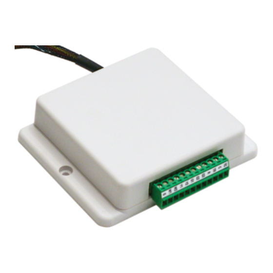
- Page 5 Stage 1 Heating 4. How to Install 1. Choose a place where to install the PAC-US444CN-1. The device provides two mounting holes that can be used to mechanically affix the case to a solid surface. Double-sided tape may be used to affix the device. When using tape, ensure that the tape is approved for use within the anticipated operating temperature ranges.
- Page 6 SW2-6: Adjusts indoor unit operation during stage 1 heating and stage 1 cooling according to the following table: SW2-6 Operation during stage 1 Full capacity The capacity is adjusted so that the room temperature is adjusted (heated or cooled) at a fixed rate. Note: When either Y2 or W2 is left unconnected, it is recommended to set SW2-6 to the OFF position. When both Y2 and W2 are connected, it is recommended to set SW2-6 to the ON position. © 2015 Mitsubishi Electric US, Inc. sandium.com...
- Page 7 *Refer to the appropriate Indoor Unit Installation Manual for Mode 23 function setting definitions. Fan Speed During Heating Mode, Thermal Off SW2-5: Adjusts Mode 25 initial setting (fan speed in thermal off for heating) according to the following table: SW2-5 Result Extra low (Default) Set by Thermostat Interface © 2015 Mitsubishi Electric US, Inc. sandium.com...
- Page 8 Additional function settings not addressed by the thermostat interface may be configured by temporarily connecting an MA remote controller. Grouping The connection of more than one PAC-US444CN-1 to a single set of thermostat dry-contacts is not supported. Temperature Sensing The PAC-US444CN-1 relies upon both the dry-contact thermostat and the indoor unit’s thermistors in order to monitor room temperature.
Need help?
Do you have a question about the PAC-US444CN-1 and is the answer not in the manual?
Questions and answers