Table of Contents
Advertisement
Quick Links
Advertisement
Table of Contents

Related Manuals for iRZ MC52PU


Summary of Contents for iRZ MC52PU
-
Page 2: Table Of Contents
Contents 1. Introduction ..........................4 1.1. Document description ........................4 1.2. Service data ........................... 4 1.3. Safety rules ............................ 4 2. General Information ........................ 5 2.1. Purpose............................5 2.2. Set ..............................5 2.3. Features............................5 2.4. Appearance ............................ 7 2.5. Interfaces ............................8 2.5.1. - Page 3 Tables Table 2.5.1: Using DB9 connector pins....................9 Table 2.5.2: Using connector power pins ................... 9 Table 2.5.3: Using USB type B connector pins ................10 Table 2.6.1: Connection status LED ....................10 Figures Fig. 2.4.1. Front view ......................... 7 Fig.
-
Page 4: Introduction
1. Introduction 1.1. Document description This manual is intended for experienced PC users. It describes the device and the operation of the GSM modem iRZ MC52PU. 1.2. Service data Document version Issue date 08.30.2013 Prepared by V.N. Golovin Approved by P.A. -
Page 5: General Information
2. General Information 2.1. Purpose iRZ MC52PU modem is an industrial GSM modem for receiving and transmitting data, text messages and faxes. It is perfectly suited both for providing mobile access to the Internet and for industrial applications including telemetry, wireless data collection from sensors, remote monitoring, control, and signaling. - Page 6 Physical characteristics: Dimensions not exceeding 69х75х26mm; Weight not exceeding 100g; Operating temperatures from -40°С to +65°С; Storage temperatures from -50°С to +85°С. Interfaces: TJ6-6P6C connector for powering the modem; USB type B connector for connecting the USB interface and power; DB9 connector (female) for connecting the RS232 interface;...
-
Page 7: Appearance
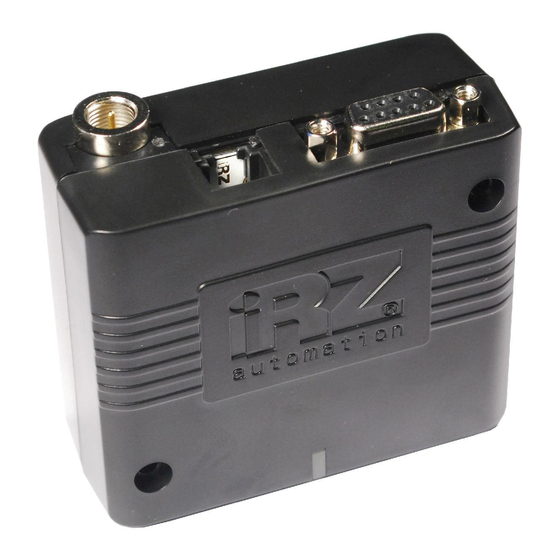
2.4. Appearance MC52PU modem is a compact device in a plastic case. Its appearance is displayed on Fig.2.4.1 and Fig.2.4.2. Fig. 2.4.1. Front view Fig. 2.4.2. Back view The numbers on Fig. 2.4.1 and Fig. 2.4.2 stand for: USB type B connector for connecting the USB interface;... -
Page 8: Interfaces
2.5. Interfaces 2.5.1. DB9 Connector (RS232) Use the connector to communicate with a controlling device, RS232 interface. Factory settings: speed – 57600 bit/s, data bits – 8, parity – none, stop bit – 1. The AT-commands are used to control the modem operation (see the module description). There are several specific features of this modem: Autobauding is not supported No DTR, DSR, DCD, RING circuits. -
Page 9: Power Connector
Table 2.5.1: Using DB9 connector pins Signal Direction Purpose Not used Shortened to the body of the system Modem-PC Received Data PC-Modem Transmitted Data PC-Modem Start and rest the modem (see chapter 3.3) General Common Ground Not used Shortened to the body of the system PC-Modem Request to Send Modem-PC... -
Page 10: Usb Type B Connector
2.5.3. USB type B connector Connector USB (type B) is used for connection to controlling the device, USB interface. USB also used for powering the modem, see chapter 3. Fig. 2.5.3. USB connector type B Table 2.5.3: Using USB type B connector pins Signal Purpose V BUS... -
Page 11: Connecting And Configuring
3.2. Connecting The modem is controlled by standard AT-commands. You can download the description of the AT-commands at www.irz.net. Before connecting the device, install the SIM card into the modem. In order to do that: Eject the SIM holder by pressing the SIM card holder ejector button (Fig.2.4.1);... -
Page 12: Control, Rebooting, And Connecting
The modem is controlled by standard AT-commands. When the modem is connected using the USB interface, a driver is needed (it can be downloaded from www.irz.net, “Support” section). After the driver is installed a virtual COM port should appear. Use the modem as any standard modem. When selecting a modem it is recommended to choose a standard 33600bps modem. -
Page 13: Fig. 3.3. Generate Id
Run SetID application ("SetID.exe" file), main application window will open (see Fig. 3.2). Click on “Найти устройство” (1) button. The bottom margin of the main window will turned to yellow (2), in strings “Устройство” (3) and “ID” (4) ID’s numbers will be displayed (see Fig. 3.2); Fig. - Page 14 When shutting down using AT-commands the modem goes into a sleeping mode (minimal energy consumption). Emergence from the sleeping mode occurs along the line of the DTR COM-port transition from a passive to an active state. Controlling the modem using the DTR line is done using the USB interface. After the driver is installed a virtual COM port should appear.
-
Page 15: Support
4. Support New document versions and software are available using: St. Petersburg The company’s website: www.radiofid.ru Phone number in St. Petersburg: +7 (812) 318 18 19 E-mail: support@radiofid.ru Moscow The company’s website: www.digitalangel.ru Phone number in Moscow: +7 (495) 974 74 22 E-mail: info@digitalangel.ru Our support team is ready to assist you with any questions you might have when installing, configuring or...
Need help?
Do you have a question about the MC52PU and is the answer not in the manual?
Questions and answers