Table of Contents
Advertisement
Quick Links
Advertisement
Table of Contents

Related Manuals for Optical Systems Design OSD2153 Series


Summary of Contents for Optical Systems Design OSD2153 Series
-
Page 1: Index
OPERATOR MANUAL OSD2153 SERIES GIGABIT ETHERNET MEDIA CONVERTER... -
Page 3: Table Of Contents
OPTICAL SYSTEMS DESIGN INDEX 1 TECHNICAL SUMMARY ......................5 BRIEF DESCRIPTION ......................5 1.1.1 OVERVIEW ......................... 5 1.1.2 APPLICATIONS ........................5 1.1.3 FEATURES AND BENEFITS ..................... 5 TYPICAL CONFIGURATION ....................6 TECHNICAL SPECIFICATIONS ................... 7 OSD2153 FRONT AND REAR PANELS ................8 INSTALLATION AND OPERATION .................. - Page 4 OPTICAL SYSTEMS DESIGN FIGURE 1: OSD2153 TYPICAL CONFIGURATIONS ................. 6 FIGURE 2: OSD2153 CONNECTORS ....................8 FIGURE 3: OSD2153 DIMENSIONS ....................10 FIGURE 4: MODULE POWER SUPPLY CONNECTIONS ..............11 FIGURE 5: FIXED RJ45 ETHERNET CONNECTORS ............... 11 FIGURE 6: LED INDICATORS ......................12 FIGURE 7: OSD2153 3-WAY DIP SWITCH ..................
-
Page 5: Technical Summary
OPTICAL SYSTEMS DESIGN 1 TECHNICAL SUMMARY BRIEF DESCRIPTION 1.1.1 OVERVIEW The OSD2153 is designed to convert between 10/100/1000Base-T copper cabling and 100/1000Base-X fiber cabling with the added feature of Link Loss Forwarding. It has one RJ45 copper port and one SFP port which can be specified by the user for one or two fiber configuration. -
Page 6: Typical Configuration
OPTICAL SYSTEMS DESIGN TYPICAL CONFIGURATION Figure 1 below indicates the typical set-up for an OSD2153 system. FIGURE 1: OSD2153 TYPICAL CONFIGURATIONS DOC ID: 10115703 PAGE 6 OSD2153 OPERATOR MANUAL... -
Page 7: Technical Specifications
OPTICAL SYSTEMS DESIGN TECHNICAL SPECIFICATIONS TABLE 1: TECHNICAL SPECIFICATIONS SPECIFICATION PERFORMANCE IEEE802.3i/802.3u/802.3ab 10/100/1000Base-T Ethernet Electrical Data Interface Electrical Data Rate 10, 100, 1000Mbps with energy detect, auto negotiate, auto MDIX 10KB Jumbo Frame Support IEEE802.3z 1000Base-Lx/Sx Optical Data Interface Optical Data Rate... -
Page 8: Osd2153 Front And Rear Panels
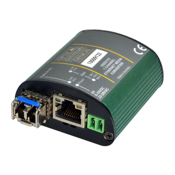
OPTICAL SYSTEMS DESIGN OSD2153 FRONT AND REAR PANELS There is one fixed copper port for 10/100/1000Base-T and one SFP port on the front panel. The SFP device is sold separately giving the user choice to use either one or two fiber communications with various optical power outputs depending on the distance required. -
Page 9: Installation And Operation
OPTICAL SYSTEMS DESIGN 2 INSTALLATION AND OPERATION INTRODUCTION This section outlines the methods required to install and operate the OSD2153 successfully. It should be studied carefully if damage to the equipment or poor results are to be avoided. This equipment has been fully tested prior to dispatch and is ready for immediate operation. However it is advisable to check for external transportation damage before operation. -
Page 10: Osd2153 Drawings And Dimensions
OPTICAL SYSTEMS DESIGN 2.2.2 OSD2153 DRAWINGS AND DIMENSIONS The OSD2153 is designed to be mounted on an even surface and to be secured by means of M4 or smaller screws. Ø3.2 21.3 51.3 51.3 49.3 FIGURE 3: OSD2153 DIMENSIONS DOC ID: 10115703... -
Page 11: Power Supply Connections
OPTICAL SYSTEMS DESIGN 2.2.3 POWER SUPPLY CONNECTIONS The OSD2153 requires external DC power. The voltage range of the OSD2153 is +8V to +35V Power should be connected to the power socket located on the front panel as indicated in Table 2. -
Page 12: Led Indicators
OPTICAL SYSTEMS DESIGN 2.2.5 LED INDICATORS FIGURE 6: LED INDICATORS TABLE 3: LED FUNCTION Function Blinking Fiber Speed: 100Mbps Fiber Speed: 1Gbps Copper Link Amber: 10Mbps No Copper Link Activity Bi-colour: 100Mbps Green: 1Gbps Full Duplex on Copper Port Half Duplex on Copper Port... -
Page 13: Controls
OPTICAL SYSTEMS DESIGN 2.2.6 CONTROLS The OSD2153 has a 3-way DIP switch to control a number of functions. Table 4 outlines the function of each switch. For correct operation, set the required switch settings before powering the unit. Fiber Speed... -
Page 14: Fitting Sfp Connectors
OPTICAL SYSTEMS DESIGN 2.2.7 FITTING SFP CONNECTORS Care should be taken when inserting/removing the SFP connectors from the SFP port as SFP modules are Electrostatic (ES) sensitive and Electrostatic Discharge (ESD) precautions should be taken when installing. Ensure that the SFP is fully engaged and latched into position. -
Page 15: Osd2153 Operation
OPTICAL SYSTEMS DESIGN OSD2153 OPERATION This section outlines the OSD2153 connections and switch settings. Read this section carefully for trouble free set up and operation. There are two possible configurations for the OSD2153 namely Single Unit Configuration and Dual Unit configuration. - Page 16 OPTICAL SYSTEMS DESIGN The following tables outline the recommended switch settings for the OSD2153. Any changes in switch settings require power up to take effect. TABLE 5: CONFIGURATION WITH LLF ENABLED Configurations Case1 Case2 Case3 Case4 Switch Setting 1. LLF detects fiber &...
- Page 17 OPTICAL SYSTEMS DESIGN Examples Figure 12 is an example of a copper connection loss. The OSD2153 will detect that there is no copper connection received and then disable the transmission to the fiber port. The 1000Base-X switch will thus be notified that there has been a copper link loss.
-
Page 18: Maintenance
OPTICAL SYSTEMS DESIGN 3 MAINTENANCE INTRODUCTION The following section outlines the fault-finding procedure for the OSD2153 modems. Please take note of the following: Personnel without appropriate training should not attempt any maintenance except that outlined ▲ below. If further maintenance is attempted you are warned that every care should be taken to ensure that ▲... -
Page 19: Warranty
For warranty period, please call your local OSD distributor. REPAIRS Optical Systems Design reserves the right to repair or replace faulty modules/units. Please obtain a “Return Material Authorisation” (RMA) form and number before returning goods. Goods must be returned in adequate packing material to Optical Systems Design, Warriewood or its nominated authorised representative, for all repairs. - Page 20 OPTIC L Optical Systems Design Pty. Ltd. 7/1 Vuko Pl. Warriewood 2102 SYSTEMS P.O. Box 891 Mona Vale N.S.W. Australia 2103 Telephone: +61 2 9913 8540 DESIGN Facsimile: +61 2 9913 8735 Email: sales@osd.com.au Web Site: www.osd.com.au PTY LTD A.B.N. 83 003 020 504...
Need help?
Do you have a question about the OSD2153 Series and is the answer not in the manual?
Questions and answers