
Subscribe to Our Youtube Channel
Related Manuals for Optical Systems Design OSD2155


Summary of Contents for Optical Systems Design OSD2155
-
Page 1: Index
OPERATOR MANUAL OSD2155 10/100/1000BaseT ETHERNET MEDIA CONVERTER CARD SUPPORTING JUMBO FRAMES... -
Page 3: Table Of Contents
INSTALLATION AND OPERATION ..................9 INTRODUCTION ........................9 INSTALLATION ........................9 2.2.1 WARNING AND PRECAUTIONS ..................9 2.2.2 OSD2155 DRAWINGS AND DIMENSIONS ..............10 2.2.3 POWER SUPPLY CONNECTIONS ................. 10 2.2.4 LOCATION ........................11 2.2.5 FIXED RJ45 COPPER PORT PIN ASSIGNMENTS ............11 2.2.6... - Page 4 FIGURE 6: FIXED RJ45 ETHERNET CONNECTORS ............... 11 FIGURE 9: FITTING/REMOVING SFP CONNECTORS ..............11 FIGURE 7: LED INDICATORS ......................12 FIGURE 8: OSD2155 3-WAY DIP SWITCH ..................13 FIGURE 10: BASIC CONNECTIONS ....................14 FIGURE 10: LINK LOSS FORWARDING FUNCTION ..............15 FIGURE 11: COPPER CONNECTION LOSS ..................
-
Page 5: Technical Summary
The unit will operate on either singlemode or multimode fiber by use of the appropriate optical device. A major benefit of the OSD2155 is its reliable operation over the -20°C to +75°C temperature range which allows it to be used in environments such as roadside cabinets, mine sites and factories. -
Page 6: Typical Configuration
OPTICAL SYSTEMS DESIGN TYPICAL CONFIGURATION Figure 1 below indicates the typical set-up for an OSD2155 system. FIGURE 1: OSD2155 TYPICAL CONFIGURATIONS DOC ID: 10117401 PAGE 6 OSD2155 OPERATOR MANUAL... -
Page 7: Technical Specifications
Relative Humidity 0 to 95% non-condensing Power Requirements +11V to +13V supplied via the card frame backplane Dimensions (mm) 25W x 169D x 100H 0.2kg Weight Chassis Current Consumption 0.25 Amp (CCC) 102215502 DOC ID: 10117401 PAGE 7 OSD2155 OPERATOR MANUAL... -
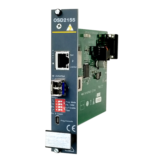
Page 8: Front Panel
Each section will be described further throughout this manual. Fixed RJ45 Copper Port SFP Port 4-Way DIP Switch Mini USB Connector FIGURE 2: OSD2155 CONNECTORS DOC ID: 10117401 PAGE 8 OSD2155 OPERATOR MANUAL... -
Page 9: Installation And Operation
2 INSTALLATION AND OPERATION INTRODUCTION This section outlines the methods required to install and operate the OSD2155 successfully. It should be studied carefully if damage to the equipment or poor results are to be avoided. This equipment has been fully tested prior to dispatch and is ready for immediate operation. However it is advisable to check for external transportation damage before operation. -
Page 10: Osd2155 Drawings And Dimensions
OPTICAL SYSTEMS DESIGN 2.2.2 OSD2155 DRAWINGS AND DIMENSIONS The standard OSD2155 is designed to be mounted and powered from either the OSD350 or OSD370 19” 3RU Chassis. FIGURE 3: DIMENSIONS 2.2.3 POWER SUPPLY CONNECTIONS The OSD2155 requires external DC power. The voltage range of the OSD2155 is +11V to +13V Which is powered from the OSD370 or OSD350 chassis. -
Page 11: Location
2.2.4 LOCATION As with any electrical device, the OSD2155 together with the OSD370/OSD350 chassis should be placed where the unit will not be subjected to extreme temperatures, humidity, or electromagnetic interference. Specifically, the site selected should meet the following requirements: •... -
Page 12: Led Indicators
Blinking Copper Speed 1Gbps Green 10/100Mbps No Copper Lnk/Act Copper Link Activity Amber Activity Link Power Power On Green Power Off 100Mbps Amber No Optical Lnk/Act/Spd Fiber Speed Activity Link 1Gbps Green DOC ID: 10117401 PAGE 12 OSD2155 OPERATOR MANUAL... -
Page 13: Controls
2.2.8 CONTROLS The OSD2155 has a 4-way DIP switch to control a number of functions. Figure 8 outlines the function of each switch. For correct operation, set the required switch settings before powering the unit. The OSD2155 also has a reset switch located on the rear panel. Press this button momentarily to reset the unit. -
Page 14: Basic Connections
OPTICAL SYSTEMS DESIGN 2.2.9 BASIC CONNECTIONS Figure 10 shows basic user connections to the OSD2155. Ethernet cable SFP Fiber cable FIGURE 9: BASIC CONNECTIONS DOC ID: 10117401 PAGE 14 OSD2155 OPERATOR MANUAL... -
Page 15: Link Loss Forwarding
OPTICAL SYSTEMS DESIGN LINK LOSS FORWARDING Figure 10 is a flow chart of the OSD2155 Link Loss Forwarding (LLF) function and operation. FIGURE 10: LINK LOSS FORWARDING FUNCTION DOC ID: 10117401 PAGE 15 OSD2155 OPERATOR MANUAL... - Page 16 OPTICAL SYSTEMS DESIGN The following tables outline the recommended switch settings for the OSD2155. Any changes in switch settings require power up to take effect. TABLE 5: CONFIGURATION WITH LLF ENABLED Configurations Case1 Case2 Case3 Case4 Switch Setting 1 2 3 4...
- Page 17 OPTICAL SYSTEMS DESIGN Examples Figure 11 is an example of a copper connection loss. The OSD2155 will detect that there is no copper connection received and then disable the transmission to the fiber port. The 1000Base-X switch will thus be notified that there has been a copper link loss.
-
Page 18: Maintenance
OPTICAL SYSTEMS DESIGN 3 MAINTENANCE INTRODUCTION The following section outlines the fault-finding procedure for the OSD2155 modems. Please take note of the following: ▲ Personnel without appropriate training should not attempt any maintenance except that outlined below. ▲ If further maintenance is attempted you are warned that every care should be taken to ensure that... -
Page 19: Warranty
For warranty period, please call your local OSD distributor. REPAIRS Optical Systems Design reserves the right to repair or replace faulty modules/units. Please obtain a “Return Material Authorisation” (RMA) form and number before returning goods. Goods must be returned in adequate packing material to Optical Systems Design, Warriewood or its nominated authorised representative, for all repairs. - Page 20 OPTIC L Optical Systems Design Pty. Ltd. 7/1 Vuko Pl. Warriewood 2102 SYSTEMS P.O. Box 891 Mona Vale N.S.W. Australia 2103 Telephone: +61 2 9913 8540 Facsimile: +61 2 9913 8735 DESIGN Email: sales@osd.com.au Web Site: www.osd.com.au PTY LTD A.B.N. 83 003 020 504...
Need help?
Do you have a question about the OSD2155 and is the answer not in the manual?
Questions and answers