Table of Contents
Advertisement
Quick Links
Copyright © 2019 by DATAQ Instruments, Inc. The Information contained herein is the exclusive property of
DATAQ Instruments, Inc., except as otherwise indicated and shall not be reproduced, transmitted, transcribed, stored
in a retrieval system, or translated into any human or computer language, in any form or by any means, electronic,
mechanical, magnetic, optical, chemical, manual, or otherwise without expressed written authorization from the com-
pany. The distribution of this material outside the company may occur only as authorized by the company in writing.
DATAQ Instruments' hardware and software products are not designed to be used in the diagnosis and treatment of
humans, nor are they to be used as critical components in any life-support systems whose failure to perform can rea-
sonably be expected to cause significant injury to humans.
DATAQ, the DATAQ logo, and W
T h e w a y P C - b a s e d i n s t r u m e n t a t i o n s h o u l d b e
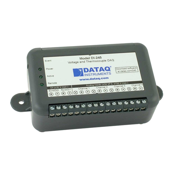
Millivolt, Voltage, and Thermocouple Data Acquisition System
D
are registered trademarks of DATAQ Instruments, Inc. All rights reserved.
IN
AQ
DATAQ Instruments, Inc.
241 Springside Drive
Akron, Ohio 44333 U.S.A.
Telephone: 330-668-1444
Fax: 330-666-5434
Designed and manufactured in the
United States of America
DI-245
User's Manual
Manual Revision G
Advertisement
Table of Contents

Related Manuals for Dataq DI-245


Summary of Contents for Dataq DI-245
- Page 1 The distribution of this material outside the company may occur only as authorized by the company in writing. DATAQ Instruments' hardware and software products are not designed to be used in the diagnosis and treatment of humans, nor are they to be used as critical components in any life-support systems whose failure to perform can rea- sonably be expected to cause significant injury to humans.
-
Page 3: Warranty And Service Policy
DATAQ Instruments, Inc. warrants that this hardware will be free from defects in materials and workmanship under normal use and service for a period of 1 year from the date of shipment. DATAQ Instruments' obligations under this warranty shall not arise until the defective material is shipped freight prepaid to DATAQ Instruments. The only responsibility of DATAQ Instruments under this warranty is to repair or replace, at its discretion and on a free of charge basis, the defective material. -
Page 5: Table Of Contents
Physical Characteristics ........................5 Software ............................. 5 3. Installation ............................7 Installing WinDaq Software and the DATAQ Instruments Hardware Manager ....... 7 Connecting the Instrument to Your Computer ................... 8 DATAQ Instruments Hardware Manager ..................8 4. Controls, Indicators, and Connections ..................... 9 Mini-B USB Connection ........................ -
Page 7: Introduction
DI-245 Hardware Manual 1. Introduction This manual contains information designed to familiarize you with the features and functions of the DI-245 USB mil- livolt, volt, and thermocouple data acquisition system. Features The DI-245 data acquisition instrument is a portable data recording module that communicates through your com- puter's USB port. -
Page 8: The Dataq Instruments Hardware Manager
Waveform Browser is free and installed when installing W Software. The DATAQ Instruments Hardware Manager Find the DATAQ Instruments Hardware Manager in the Start menu under the W program group called DATAQ Instruments Hardware Manager. Access W Acquisition software and manage multiple DATAQ Instruments devices in this easy-to-use point and click environment. -
Page 9: Specifications
DI-245 Hardware Manual 2. Specifications Analog Inputs Number of Channels: Channel Configuration: Differential, Isolated Programmable measurements per channel: Voltage, Thermocouple Programmable thermocouple types and measure- TC Type Temperature Measure- Accuracy (°C) ment range per channel: ment range (°C) Over 25 ±3 °C ambient temperature range. -
Page 10: Digital Inputs
DI-245 Hardware Manual Absolute max input without damage: 120 Vrms Maximum common mode voltage: 120 Vrms Minimum common mode rejection (330 unbalance): >110 db (DC to 60 Hz) Channel-to-channel crosstalk rejection: > 100 db ≤ 330 Ω; Freq ≤ 60 Hz) -
Page 11: Indicators, Connections, Controls
Desktop; bulkhead Dimensions: 2.625D × 5.5W × 1.53H in. (6.67D × 13.97W × 3.89H cm.) Weight: 4 ounces, 114 grams Software WinDaq software: Click for supported operating systems Programming: DATAQ Instruments Dot Net SDK, Instrument protocol, DLL, and ActiveX Control Specifications... -
Page 13: Installation
A DATAQ Instruments screwdriver for signal lead connections. If an item is missing or damaged, call DATAQ Instruments at 330-668-1444. We will guide you through the appropri- ate steps for replacing missing or damaged items. Save the original packing material in the unlikely event that your unit must, for any reason, be sent back to DATAQ Instruments. -
Page 14: Connecting The Instrument To Your Computer
Connecting the Instrument to Your Computer Connect the DI-245 to your computer’s USB port using the provided USB cable. No external power is required. Con- nect one end of the communications cable to the instrument port and the other to your PC’s port. -
Page 15: Controls, Indicators, And Connections
Digital In Channels Analog In Channels Please note: The SD card slot is not used in the DI-245. Allowing foreign materials to enter the device through the SD card slot may result in damage to the instrument. Mini-B USB Connection Use the supplied USB cable to connect and power the instrument through your computer’s USB port. -
Page 16: Connect Analog Input Channel 1
Run WinDaq Acquisition software for a real-time display of sampled data. Connecting Signal Leads To connect signal leads to the DI-245: Insert the stripped end of a signal lead into the desired terminal directly under the screw. Tighten the pressure flap by rotating the screw clockwise with a screwdriver. Make sure that the pressure flap tightens only against the signal wire and not the wire insulation. -
Page 17: Gain Settings For Voltage Measurements
DI-245 Hardware Manual Gain Settings for Voltage Measurements Each analog input channel on the DI-245 may be programmed for one of 12 gain ranges. Measurement Range Gain Setting ±50V Full Scale ±25V Full Scale ±10V Full Scale ±5V Full Scale ±2.5V Full Scale... - Page 18 Thermocouple Measurements Each analog input channel on the DI-245 may be programmed for one of 8 possible thermocouple types (B, E, J, K, N, R, S, or T). Change the thermocouple type for each channel individually: Select the channel (click on the channel box in the left hand side of the waveform screen).
-
Page 19: Digital Inputs
1.8 V. Switch Closure 30V Max 1.8V Threshold Remote Events (Evnt/DI0) Connect signal leads to the appropriate Remote Control Event terminals on the DI-245 to use a switch closure or TTL signal to record W Event Markers. Model DI-245 Event... - Page 20 DI-245 Hardware Manual Place event markers in your data file manually by pressing the push button on the DI-245 Instrument. You must enable Remote Events in W to use the button (use the menu command Options > Remote Events + or Options >...
-
Page 21: Windaq Remote Storage (Rcrd/Di1)
DI-245 Hardware Manual Remote Storage (Rcrd/DI1) Connect signal leads to the appropriate Remote Control Record terminals on the DI-245 to use a switch closure or TTL signal to start/stop recording data remotely. Model DI-245 Event Voltage and Thermocouple DAQ Power Download software at run.dataq.com... -
Page 23: Di-245 Block Diagram
DI-245 Hardware Manual 5. DI-245 Block Diagram DC/DC Range Select ÷ 1 ÷ 100 Gain Control Burnout 32-Bit Micro-controller Active Power Remote Start/Stop 4.7K Remote Remote Events Event 4.7K Terminal Panel Block Diagram... -
Page 25: Dimensional Drawing
DI-245 Hardware Manual 6. Dimensional Drawing 1.612" 2.625" 0.750" 4.250" 4.750" 5.500" Dimensional Drawing... - Page 28 DATAQ Instruments, Inc. 241 Springside Drive Akron, Ohio 44333 Telephone: 330-668-1444 Fax: 330-666-5434 Submit a support ticket to: www.dataq.com/ticket Product Quick Links: Data Acquisition | Data Loggers...
Need help?
Do you have a question about the DI-245 and is the answer not in the manual?
Questions and answers