Table of Contents
Advertisement
Quick Links
Copyright © 2020 by DATAQ Instruments, Inc. The Information contained herein is the exclusive property of
DATAQ Instruments, Inc., except as otherwise indicated and shall not be reproduced, transmitted, transcribed, stored
in a retrieval system, or translated into any human or computer language, in any form or by any means, electronic,
mechanical, magnetic, optical, chemical, manual, or otherwise without expressed written authorization from the com-
pany. The distribution of this material outside the company may occur only as authorized by the company in writing.
DATAQ Instruments' hardware and software products are not designed to be used in the diagnosis and treatment of
humans, nor are they to be used as critical components in any life-support systems whose failure to perform can rea-
sonably be expected to cause significant injury to humans.
DATAQ, the DATAQ logo, and W
DI-4108 and DI-4208
8-Channel High Speed Data Acquisition Systems with Programmable Gain,
Expandability with ChannelStretch™, and Stand-alone Capability
D
are registered trademarks of DATAQ Instruments, Inc. All rights reserved.
IN
AQ
DATAQ Instruments, Inc.
241 Springside Drive
Akron, Ohio 44333 U.S.A.
Telephone: 330-668-1444
Fax: 330-666-5434
Designed and manufactured in the
United States of America
T h e w a y P C - b a s e d i n s t r u m e n t a t i o n s h o u l d b e
User's Manual
Manual Revision G
Advertisement
Table of Contents

Subscribe to Our Youtube Channel
Related Manuals for Dataq DI-4108


Summary of Contents for Dataq DI-4108
- Page 1 The distribution of this material outside the company may occur only as authorized by the company in writing. DATAQ Instruments' hardware and software products are not designed to be used in the diagnosis and treatment of humans, nor are they to be used as critical components in any life-support systems whose failure to perform can rea- sonably be expected to cause significant injury to humans.
-
Page 3: Warranty And Service Policy
DATAQ Instruments, Inc. warrants that this hardware will be free from defects in materials and workmanship under normal use and service for a period of 1 year from the date of shipment. DATAQ Instruments' obligations under this warranty shall not arise until the defective material is shipped freight prepaid to DATAQ Instruments. The only responsibility of DATAQ Instruments under this warranty is to repair or replace, at its discretion and on a free of charge basis, the defective material. -
Page 5: Table Of Contents
DI-4108 and DI-4208 Hardware Manual Table of Contents Warranty and Service Policy ........................ iii 1. Introduction ............................1 Features .............................. 1 Analog Inputs ............................ 1 Digital I/O ............................2 Software ............................. 2 WinDaq® Recording and Playback Software ................2 Help ............................. 2 2. -
Page 7: Introduction
Gain measurement ranges of ±200, ±500 mV, ±1, ±2, ±5, ±10 Volts for the DI-4108 or ±2, ±5, ±10, ±20, ±50, ±100 Volts for the DI-4208 are programmable on a per channel basis. Ana- log channels are protected to 120 V rms. -
Page 8: Digital I/O
WinDaq software. Each port may be configured as a switch using either the provided protocol or .Net class. Software All software required to record and playback waveforms is included with the purchase of any DI-4108 or 4208 data acquisition system via download. Use the WinDaq Dashboard to access WinDaq Acquisition software or to setup the stand-alone configuration. -
Page 9: Specifications
Analog Inputs Number of Channels: Channel Configuration: Differential Measurement range per channel: DI-4108: Programmable ±200, ±500 mV, ±1, ±2, ±5, ±10 V DI-4208: Programmable ±2, ±5, ±10, ±20, ±50, ±100 V Input impedance: DI-4108: 100 k differential DI-4208: 795 k differential Absolute accuracy: 0.25% of full scale range @ 25°C, excluding common mode error... - Page 10 Channel skew between any 2 units: 10 µS, typical Synchronization Conditions: Syncs with any combination of DI-1120, DI-4108, DI-4208, and DI- 4718B USB instruments. All synced instruments must operate at the same sample rate per channel, regardless of channel number, type, or range.
- Page 11 ≥50 kHz (higher speeds may result in data loss) Channel skew between any 2 units: 10 µS, typical Synchronization Conditions: Syncs with any combination of DI-1120, DI-4108, DI-4208, and DI- 4718B Ethernet instruments. For most accurate synchronization, all instruments should be connected to the same Ethernet switch.
-
Page 13: Installation
DI-4108 and DI-4208 Hardware Manual 3. Installation The following items are included with each DI-4108 or DI-4208 USB Data Acquisition System. Verify that you have the following: • A DI-4108 or DI-4208 USB data acquisition instrument. • 6-foot USB cable; Ethernet versions also provide a 5-foot Ethernet cable and an AC power supply if required (PoE versions do not come with a power supply). -
Page 14: Connect The Instrument To Your Computer
Connect the Instrument to Your Computer All DI-4108 and DI-4208 instruments can be connected to your computer’s USB port using the provided USB cable. No external power is required when connected via the USB port. Connect one end of the communications cable to the instrument port and the other to your PC’s port. -
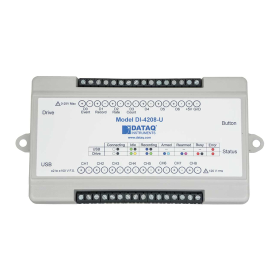
Page 15: Controls, Indicators, And Connections
DI-4108 and DI-4208 Hardware Manual 4. Controls, Indicators, and Connections Digital Ports 0-6 +5V Out Ground Even Marker USB Drive 0-25V Max Push Button +5V GnD Drive Event Record Rate Count Model DI-4108 or DI-4208 Button Bulkhead Bulkhead www.dataq.com Ethernet... -
Page 16: Di-4108 Signal Connections
DI-4108 and DI-4208 Hardware Manual DI-4108 Signal Connections Refer to the following for screw terminal port identification. 0-25V Max +5V GnD Drive Event Record Rate Count Model DI-4108 Button www.dataq.com Ethernet Status ±200mV to ±10 V F.S. 120 V rms Ch#: Analog channels 1-8 (Programmable ±200, ±500 mV, ±1, ±2, ±5, ±10 Volts, 120 V rms max.) -
Page 17: Gnd: Ground
GnD: Ground. Connecting Signal Leads Connect signal leads to the DI-4108 or DI-4208: Insert the stripped end of a signal lead into the desired terminal directly under the screw. Tighten the pressure flap by rotating the screw clockwise with a small screwdriver. Make sure that the pressure flap tightens only against the signal wire and not the wire insulation. - Page 18 DI-4108 and DI-4208 Hardware Manual Use the following diagram to connect Analog Input Channel 1. 0-25V Max +5V GnD Event Record Rate Count Drive Model DI-4108 or DI-4208 Button www.dataq.com Ethernet Status ±2 to ±100 V F.S. 120 V rms...
-
Page 19: Low-Pass Filter
Resolution as a Function of Sample Rate The resolution of the DI-4108 and DI-4208 is a function of sample rate. The lower the sample rate the higher the res- olution. ADC resolution (R) is a function of selected sample rate per channel (F), and the number of enabled analog... -
Page 20: Digital Ports
Digital Ports The DI-4108 and DI-4208 contain 7 general-purpose digital ports. Each digital port can be configured as a digital input or used as a switch to control an external load (up to 25 V and 100 mA). Many of the ports also provide specific func- tionality in W or a third-party program. -
Page 21: Windaq Remote Events (D0 Event)
Remote Events (D0 Event) To use a switch closure or TTL signal to record W Event Markers, connect signal leads to the appropriate Remote Control Event terminals on the DI-4108 or DI-4208 as shown below. Signal + Signal - 0-25V Max... - Page 22 DI-4108 and DI-4208 Hardware Manual Event markers may also be placed in your data file manually by pressing the push button on the instrument. You must enable Remote Events in W to use the button (use the menu command Options > Remote Events +or Options >...
-
Page 23: Windaq Remote Storage (D1 Record)
DI-4108 and DI-4208 Hardware Manual Remote Storage (D1 Record) To use a switch closure or TTL signal to begin recording data remotely, connect signal leads to the appropriate Remote Control Record terminals on the DI-4108 or DI-4208 as shown below. Signal + Signal -... - Page 24 Rate channel. Click on the Channel 10 channel box to enable/disable Rates. The Channel 10 channel box will display an “R” when enabled. Connect any TTL pulse stream (25 VDC max) to the D2 Rate channel on the DI-4108 or DI-4208. Signal +...
-
Page 25: Windaq Counter (D3 Count)
DI-4108 and DI-4208 Hardware Manual measure the output of a flow meter that can measure a maximum flow rate of 100 gallons per minute, and the output frequency at that rate is 100 Hz, you would choose the 100 Hz range setting. A range setting of 200 Hz full scale sac- rifices half of the instrument's resolution at 200 gallons per minute, and a range of 50 Hz allows measurements to only 50 gallons per minute full scale. - Page 26 DI-4108 and DI-4208 Hardware Manual Acquisition menu to open the Channel Selection grid. Channel 11 is the designated Count channel. Click on the Channel 11 channel box to enable/disable Counts. The Channel 11 channel box will display a “C” when enabled.
-
Page 27: General Purpose Digital Inputs
DI-4108 and DI-4208 Hardware Manual Connect any TTL pulse stream (25 VDC max) to the D3 Count channel on the DI-4108 or DI-4208. Signal + Signal - 0-25V Max +5V GnD Drive Event Record Rate Count Model DI-4108 or DI-4208 Button www.dataq.com... -
Page 28: General Purpose Digital Outputs
DI-4108 and DI-4208 Hardware Manual Channel 9 records and displays all the digital inputs, even the state of the Rate and Count inputs if those channels are enabled. With Channel 9 selected in the display window click Scaling > Digital Plot to show a digital display and make the data more meaningful on screen. -
Page 29: 4-20Ma Current Loop Measurements
DI-4108 and DI-4208 Hardware Manual 4-20mA Current Loop Measurements Use the following diagram for 4-20mA current loop measurement connections. 0-25V Max +5V GnD Drive Event Record Rate Count Model DI-4108 or DI-4208 Button www.dataq.com Ethernet Status ±2 to ±100 V F.S. -
Page 30: Mode Led Indicator
EU Tag Upper Level Lower Level Visit our website at http://www.dataq.com/blog/data-acquisition/4-20-ma-current-loop-measurements/ to address all popular 4-20mA configurations. You can also associate these values to a physical measurement such as pressure, load, flow, torque, etc. Read the Help files for more information regarding Engineering Units Settings. -
Page 31: Control Button Operations
DI-4108 and DI-4208 Hardware Manual Acquiring Data WinDaq Acquisition Software is running and the device is acquiring data to your PC via the Ethernet interface. to PC via Ethernet Interface Blinking Blue/ Yellow Recording Data The device is acquiring data and recording to your USB thumb drive. -
Page 32: Stop Recording To Usb Thumb Drive
Switching between LibUSB and CDC Modes The native communication mode of DI-4108 and DI-4208 instruments is LibUSB but it can be switched to the USB CDC (Communication Device Class). CDC mode allows the USB port of DI-4108 and DI-4208 devices to appear like a traditional RS-232 port, which is common across most operating systems and development languages. -
Page 33: Apply Ethernet And Stand-Alone Configuration To Device
DI-4108 and DI-4208 Hardware Manual Apply Ethernet and Stand-alone Configuration to Device Load Ethernet settings or stand-alone configuration settings using the Control Button. Ethernet and Stand-alone configurations can also be applied via the Dashboard (preferred method). Device must be in Idle mode for Ethernet or USB thumb Drive (mode LED blinks green/yellow). -
Page 34: Channelstretch
USB devices via the USB interface. The DI-4718B-E can also synchronize with other Ethernet instruments via the Ethernet interface. Connect up to 16 DI-4718B, DI-1120, DI-4108, and/or DI-4208 devices with a powered USB hub (or multiple cascaded/connected powered USB hubs) or Ethernet switch to record more than 8 channels of data to a single WinDaq file. -
Page 35: Connection
DI-4108 and DI-4208 Hardware Manual Connection All USB devices must be on the same USB controller (or hub)* in order to synchronize data acquisition. All Ethernet devices must be on the same subnet as the PC that is recording the data (preferably the same Ethernet switch). -
Page 36: Channel Selection
DI-4108 and DI-4208 Hardware Manual Channel Selection Devices are listed in the Channel Selection grid in alpha-numeric order of the serial numbers of the device. Devices must be connected to the USB hub before starting WinDaq. Controls, Indicators, and Connections... -
Page 37: Unlock Windaq Or Stand-Alone
5. Unlock WinDaq The DI-4108 and DI-4208 will record up to four channels using WinDaq/Lite software and a single channel to the USB thumb drive. An unlock code is required to record more than 4 channels or to use ChannelStretch™ to synchro- nize multiple instruments (unlock code required for each unit to be synchronized). - Page 38 DI-4108 and DI-4208 Hardware Manual Click on the Yes button to enter your code. Click on the No button to go to Stand-alone configuration for a single channel. Enter the Key in the appropriate dialog boxes. Click OK. Unlock WinDaq...
-
Page 39: Dimensional Drawing
DI-4108 and DI-4208 Hardware Manual 6. Dimensional Drawing Top View Side View All dimensions in inches Dimensional Drawing...
Need help?
Do you have a question about the DI-4108 and is the answer not in the manual?
Questions and answers