Table of Contents
Advertisement
Copyright © 2019 by DATAQ Instruments, Inc. The Information contained herein is the exclusive property of
DATAQ Instruments, Inc., except as otherwise indicated and shall not be reproduced, transmitted, transcribed, stored
in a retrieval system, or translated into any human or computer language, in any form or by any means, electronic,
mechanical, magnetic, optical, chemical, manual, or otherwise without expressed written authorization from the com-
pany. The distribution of this material outside the company may occur only as authorized by the company in writing.
DATAQ Instruments' hardware and software products are not designed to be used in the diagnosis and treatment of
humans, nor are they to be used as critical components in any life-support systems whose failure to perform can rea-
sonably be expected to cause significant injury to humans.
DATAQ, the DATAQ logo, and W
T h e w a y P C - b a s e d i n s t r u m e n t a t i o n s h o u l d b e
8-Channel USB Voltage and Thermocouple Data Acquisition System
D
are registered trademarks of DATAQ Instruments, Inc. All rights reserved.
IN
AQ
DATAQ Instruments, Inc.
241 Springside Drive
Akron, Ohio 44333 U.S.A.
Telephone: 330-668-1444
Fax: 330-666-5434
Designed and manufactured in the
United States of America
DI-2008
User's Manual
Manual Revision C
Advertisement
Table of Contents

Subscribe to Our Youtube Channel
Related Manuals for Dataq DI-2008


Summary of Contents for Dataq DI-2008
- Page 1 The distribution of this material outside the company may occur only as authorized by the company in writing. DATAQ Instruments' hardware and software products are not designed to be used in the diagnosis and treatment of humans, nor are they to be used as critical components in any life-support systems whose failure to perform can rea- sonably be expected to cause significant injury to humans.
-
Page 3: Warranty And Service Policy
DATAQ Instruments, Inc. warrants that this hardware will be free from defects in materials and workmanship under normal use and service for a period of 1 year from the date of shipment. DATAQ Instruments' obligations under this warranty shall not arise until the defective material is shipped freight prepaid to DATAQ Instruments. The only responsibility of DATAQ Instruments under this warranty is to repair or replace, at its discretion and on a free of charge basis, the defective material. -
Page 5: Table Of Contents
Connect the Instrument to Your Computer ..................8 4. Controls, Indicators, and Connections ..................... 9 Mini-B USB Connection ........................9 Screw Terminals ..........................9 DI-2008 Signal Connections ....................... 10 Connecting Signal Leads ......................10 Analog Inputs ..........................11 Gain Settings for Voltage Measurements ................... 12 Thermocouple Measurements ..................... -
Page 7: Introduction
Digital I/O The DI-2008 contains seven digital ports that may each be used as a general-purpose digital input or for a specific function as designated on the device. Digital port D0 may be used for WinDaq Events; Digital port D1 may be used for WinDaq remote Start/Stop;... -
Page 8: Software
DI-2008 Hardware Manual counts; Digital ports D4-D6 are general-purpose digital input ports. Please Note: Digital outputs are not supported in WinDaq software. Each port may be configured as a switch using your own program. Software All software required to record and playback waveforms is included with the purchase of any DI-2108-P data acqui- sition system via download. -
Page 9: Specifications
DI-2008 Hardware Manual 2. Specifications Analog Inputs Number of Channels: Channel Configuration: Differential, Isolated Programmable measurements per channel: Voltage, Thermocouple Programmable thermocouple types and measure- TC Type Range (°C) Accuracy (°C) ment range per channel: -190 to 1200 ±(0.1% of span + 2) Over 25 ±3 °C ambient temperature range. - Page 10 DI-2008 Hardware Manual Maximum common mode voltage: 120 Vrms Minimum common mode rejection (330 unbalance): >110 dB (DC to 60 Hz) Channel-to-channel crosstalk rejection: > 100 dB ≤ 330 Ω; Freq ≤ 60 Hz) source source Digital Ports Number of ports:...
- Page 11 DI-2008 Hardware Manual Minimum temperature measurement resolution: TC Type Resolution Units 0.086 0.096 0.037 0.096 °C 0.111 0.073 0.092 4-20 mA current loop resolution: 13,100 ADC counts over the 4-20 mA range (5 VFS range with 250 shunt resistor) Maximum sample throughput rate:...
- Page 12 Desktop; bulkhead Dimensions: 6.68W × 3.28D × 1.13H in. (169.67W × 83.13D × 28.7H cm.) Weight: 5.7 ounces (162 grams) Software WinDaq software: Click for supported operating systems Programming: DATAQ Instruments Dot Net SDK, Instrument protocol, DLL, and ActiveX Control Specifications...
-
Page 13: Installation
DI-2008 Hardware Manual 3. Installation The following items are included with each DI-2008 USB Data Acquisition System. Verify that you have the follow- ing: • A DI-2008 USB data acquisition instrument. • 6-foot USB cable. • A DATAQ Instruments screwdriver for signal lead connections. -
Page 14: Connect The Instrument To Your Computer
Connect the Instrument to Your Computer DI-2008 instruments can be connected to your computer’s USB port using the provided USB cable. No external power is required. Connect one end of the communications cable to the instrument port and the other to your PC’s port. -
Page 15: Controls, Indicators, And Connections
Connection Analog In Channels 1-8 Please note: The Micro SD card slot is not used in the DI-2008 Allowing foreign materials to enter the device through the Micro SD card slot may result in damage to the instrument. Mini-B USB Connection Use the supplied USB cable to connect and power the instrument through your computer’s USB port. -
Page 16: Di-2008 Signal Connections
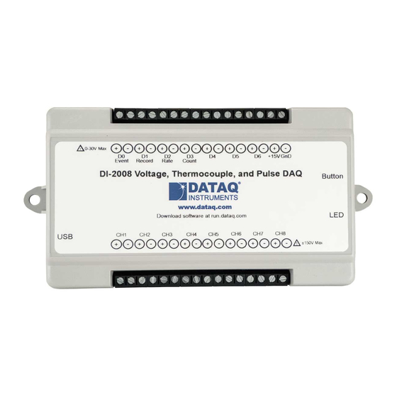
+15V GnD Event Record Rate Count 60mA max DI-2008 Voltage, Thermocouple, and Pulse DAQ Button www.dataq.com Download software at run.dataq.com 120V rms max CH#: Analog channels 1-8 (Programmable ±10, ±25, ±50, ±100, ±250, ±500mV; ±1, ±2.5, ±5, ±10, ±25, ±50 Volts or Thermocouple type J, K, T, B, R, S, E, N;... -
Page 17: Analog Inputs
Use the following diagram to connect Analog Input Channel 1. 0-30V Max +15V GnD Event Record Rate Count 60mA max DI-2008 Voltage, Thermocouple, and Pulse DAQ Button www.dataq.com Download software at run.dataq.com 120V rms max Signal + Signal - Controls, Indicators, and Connections... -
Page 18: Gain Settings For Voltage Measurements
DI-2008 Hardware Manual Gain Settings for Voltage Measurements Each analog input channel on the DI-2008 may be programmed for one of 12 gain ranges. Measurement Range Gain Setting ±50V Full Scale ±25V Full Scale ±10V Full Scale ±5V Full Scale ±2.5V Full Scale... -
Page 19: Thermocouple Measurements
Thermocouple Measurements Each analog input channel on the DI-2008 may be programmed for one of 8 possible thermocouple types (B, E, J, K, N, R, S, or T). Change the thermocouple type for each channel individually: Select the channel (click on the channel box in the left hand side of the waveform screen). -
Page 20: Digital Ports
Digital Ports The DI-2008 contains 7 general-purpose digital ports. Each digital port can be configured as a digital input or used as a switch to control an external load (up to 30 V and 100 mA). Many of the ports also provide specific functionality in or a third-party program. - Page 21 Event input. Event markers may also be placed in your data file manually by pressing the push button on the DI-2008 Instrument. You must enable Remote Events in W to use the button (use the menu command Options > Remote Events +or Options >...
-
Page 22: Windaq Remote Storage (D1 Record)
Remote Storage (D1 Record) To use a switch closure or TTL signal (30 VDC max) to begin recording data remotely, connect signal leads to the appropriate Remote Control Record terminals on the DI-2008 as shown below. Signal + Signal -... - Page 23 Rate channel. Click on the Channel 10 channel box to enable/disable Rates. The Channel 10 channel box will display an “R” when enabled. Connect any TTL pulse stream (30 VDC max) to the D2 Rate channel on the DI-2008. Signal +...
-
Page 24: Windaq Counter (D3 Count)
DI-2008 Hardware Manual measure the output of a flow meter that can measure a maximum flow rate of 100 gallons per minute, and the output frequency at that rate is 100 Hz, you would choose the 100 Hz range setting. A range setting of 200 Hz full scale sac- rifices half of the instrument's resolution at 200 gallons per minute, and a range of 50 Hz allows measurements to only 50 gallons per minute full scale. - Page 25 DI-2008 Hardware Manual Acquisition menu to open the Channel Selection grid. Channel 11 is the designated Count channel. Click on the Channel 11 channel box to enable/disable Counts. The Channel 11 channel box will display a “C” when enabled. The counter channel accumulates counts over time whether recording or in standby mode as soon as the Counter channel is enabled.
-
Page 26: General Purpose Digital Inputs
DI-2008 Hardware Manual Connect any TTL pulse stream (30 VDC max) to the D3 Count channel on the DI-2008. Signal + Signal - 0-30V Max +15V GnD Event Record Rate Count 60mA max DI-2008 Voltage, Thermocouple, and Pulse DAQ Button www.dataq.com... -
Page 27: General Purpose Digital Outputs
DI-2008 Hardware Manual Channel 9 records and displays all the digital inputs, even the state of the Rate and Count inputs if those channels are enabled. With Channel 9 selected in the display window click Scaling > Digital Plot to show a digital display and make the data more meaningful on screen. -
Page 28: 4-20Ma Current Loop Measurements
EU Tag Upper Level Lower Level Visit our website at https://www.dataq.com/blog/data-acquisition/4-20-ma-current-loop-measurements/ to address all popular 4-20mA configurations. You can also associate these values to a physical measurement such as pressure, load, flow, torque, etc. Read the Help files for more information regarding Engineering Units Settings. -
Page 29: Led Indicator
ChannelStretch™ Connect up to 16 DI-2008 devices with a powered USB hub (or multiple cascaded/connected powered USB hubs) to record more than 8 channels of data to a single WinDaq file. This provides a total of up to 128 analog channels and 112 digital ports. -
Page 30: Channel Selection
DI-2008 Hardware Manual *Please Note: Because of the way Windows operating systems manage USB controllers, the only way to be absolutely sure you are on the same controller is to use a powered USB hub. Channel Selection For multiple instruments to properly synchronize the following conditions must be met. - Page 31 DI-2008 Hardware Manual In instances where you will record two or more analog channels, enable the same total number of analog channels in each device and the same total number of digital channels in each device. In instances where you have enabled less than two analog channels (including none), you must have the same total number of channels enabled.
-
Page 32: Sample Rate
Sample Rate The sample rate for DI-2008 devices when only a single analog channel or less per device is enabled is set as a per channel sample rate or “Sample Rate/Channel.” Select Edit > Sample Rate in the main menu or press F3. -
Page 33: Unlock Windaq
DI-2008 Hardware Manual 5. Unlock WinDaq The DI-2008 will record data from a single device without feature limitations using WinDaq/Lite software. An unlock code is required to record data from more than one device. Go to https://www.dataq.com/products/di-2008/ to purchase the unlock code (click on the Accessories tab) or call 330-668-1444. Once purchased, you will be given a Key code to enter into WinDaq. -
Page 35: Dimensional Drawing
DI-2008 Hardware Manual 6. Dimensional Drawing Top View Side View All dimensions in inches Dimensional Drawing... - Page 38 DATAQ Instruments, Inc. 241 Springside Drive Akron, Ohio 44333 Telephone: 330-668-1444 Fax: 330-666-5434 E-mail: support@dataq.com Direct Product Links (click on text to jump to page) Data Acquisition | Data Logger...
Need help?
Do you have a question about the DI-2008 and is the answer not in the manual?
Questions and answers