
Summary of Contents for Procomcure Phoenix-Pure32
- Page 1 Phoenix-Pure32 Nucleic Acid Purification System Operation Manual v 1.0 Procomcure Biotech GmbH Breitwies 1 A-5305 Thalgau www.procomcure.com office@procomcure.com...
- Page 2 Foreword Thank you for purchasing the Phoenix-Pure32 Nucleic Acid Purification System. This manual describes the function and operation of then instrument. In order to use the instrument properly, please read this manual carefully before operating the device. Keep it with your device in case you encounter handling issues while operating.
- Page 3 • Disconnect the power cord from the jack at once in the following cases, and contact Procomcure Biotech: o Liquid enters the instrument. o Instrument became wet.
-
Page 4: Table Of Contents
Chapter 3 Basic Operating Instructions ............... 7 3.1. Structures ......................7 Chapter 4 Operations .................... 9 4.1. Power Connection ..................9 4.2. Installation of Phoenix-Pure32 ................ 9 4.3 Kits Installation ....................9 4.4. Install the Magnetic Rod Cover ..............10 4.5. Detailed Operations ..................10 4.5.1. -
Page 5: Chapter 1 Introduction
The operation is automatic, fast, and simple. Users can extract 1 to 32 samples simultaneously in 15-40 minutes with special kits. Phoenix-Pure32 can extract samples of animal/plant tissue, blood and body fluids etc. with different kinds of magnetic bead nucleic acid extraction reagents. It is mainly used for the extraction and purification of nucleic acid from human body samples. -
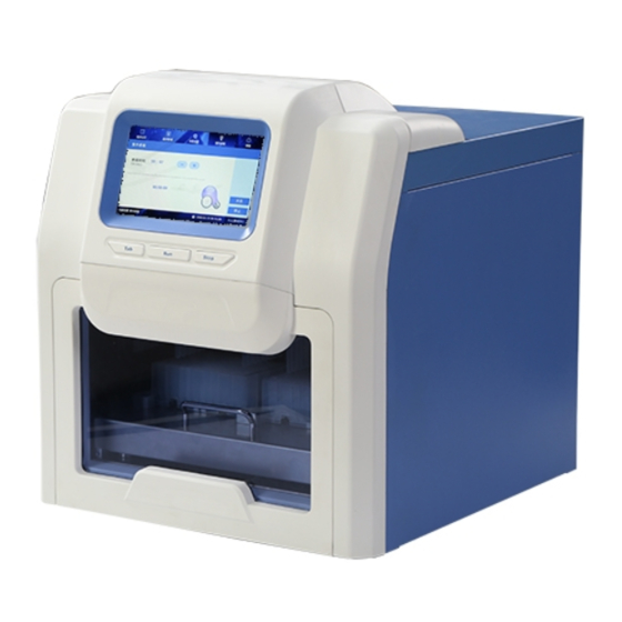
Page 6: Overall Dimensions
Vibrate and mix 10 different speeds Operation 7-inch color touch screen, mouse can be connected 8 groups of programs are pre-installed, can store 100 Programs custom programs Create, edit, save as, delete, model program Program management Extension interface With USB port and Ethernet port Network Extendable Ethernet remote control, WiFi function. -
Page 7: Chapter 3 Basic Operating Instructions
Chapter 3 Basic Operating Instructions This chapter mainly introduces structures, basic operation keys, displays as well as preparations before starting up. Please read this chapter carefully before using this instrument. 3.1. Structures 3.1.1. Front 3.1.2 Back... - Page 8 3.1.3. Inside View 3.1.4. Operation Panel Display screen: Touch screen, mouse also can be connected for operation. TAB: Select shortcut program. RUN: Start the shortcut program and run the instrument. STOP: Stop the operation.
-
Page 9: Chapter 4 Operations
4.1. Power Connection AC 100 - 240V 4.2. Installation of Phoenix-Pure32 Take out the instrument from the packaging carton and tear off the tape on the edge of the operation window, then open it and take out the foam. Screw out the screw of position ①... -
Page 10: Install The Magnetic Rod Cover
4.4. Install the Magnetic Rod Cover Insert the magnetic rod cover completely on the mounting groove. The installation quantity depends on the reagent kit number. Up to 4 pieces can be installed. 4.5. Detailed Operations 4.5.1. Start-up Interface Turn on the instrument and make sure the drawer is closed before start. The start-up interface will come up. -
Page 11: Shortcut Mode
4.5.2. Short Cut Mode Under the shortcut mode, select the program needed and click “Run”, it will enter into the program run interface. The program can also be selected by press “Tab” button on the panel and then press “Run” for start or “Stop” for terminate. On the left side, the current step info is shown. -
Page 12: List Mode
4.5.3. List Mode Select the program and click "Run" to enter the run interface. Click “View” to enter the check interface. Click “Run” to enter the running interface. Click “Option” to view the parameter setting of the program. Click “Back” to previous interface. 4.5.4 Lamp At the bottom of interface, the icon “... -
Page 13: Program Management
4.5.5 Program Management Click “Manage prog” to open program management. 4.5.5.1 Shortcut Operation Check the Shortcut Box of the program in the “Manage Prog.” interface and the program will be displayed in the “Shortcut” list interface. If the lock icon is “ ”, the program cannot be edited, deleted and saved as. - Page 14 Click “Insert” to add a new step. Click “Well” to fix the well number, then input the program name, waiting time, mixing time, magnetic time and sample volume. At the end, please click the mixing speed to select the speed. Only well location 1,6, 7 &...
-
Page 15: System Settings
4.5.6 System Settings Click “Settings” and enter the System Setting surface. 4.5.6.1 Instrument Click “Instrument” to enter the right password and then enter the setting interface to set the parameters of instrument. Remark: Usually, there is no need to change instrument parameters as instrument has already been set correctly before factory dispatch. - Page 16 4.5.6.4 Air ejector fan Click “Air Ejector Fan” to enter the fan setting. 4.5.6.5 Im.&export Click “Import/Export” and insert USB drive to finish the step. 4.5.6.6 Upgrade Click “Upgrade” to enter the right password and enter the interface. Insert a USB drive to operate.
-
Page 17: Uv Sterilization
4.5.7 UV Sterilization Click “UV sterilization” and enter numbers or click “+” “-”to set the time. Click “Start” start the sterilization process. Click “Stop” to stop the UV sterilization. During sterilization, the UV light will automatically stop when the drawer is opened. It will continue after the drawer is closed. -
Page 18: Chapter 5 Trouble Shooting
Chapter 5 Trouble Shooting 5.1. Troubleshooting Error Causes Solution Power not Check power connected Switch failure Replace Switch No display after switching on Replace Fuse (5X20 Fuse failure 250V 8A) Others Contact PCC Replace light tube No UV light UV light failure Contact PCC Replace light tube No Light... -
Page 19: Software Error Alarm List
5.2. Software Error Alarm List Error Type Error Name Error Code T1,T2,T3,T4,T5,T6, E011,E021,E031,E041, T7,T8Overheat E051,E061,E071,E081 T1,T2,T3,T4,T5,T6, E018,E028,E038,E048, T7,T8Drive circuit fault E058,E068,E078,E088 T1,T2,T3,T4,T5,T6, E015,E025,E035,E045, T7,T8Open circuit E055,E065,E075,E085 Temperature (Code: 0) T1,T2,T3,T4,T5,T6, E016,E026,E036,E046, T7,T8Short circuit E056,E066,E076,E086 The drive circuit of E019 exhaust fan fault The drive circuit of E009 cooling fan fault... -
Page 20: Chapter 7 Abbreviations And Tags
Chapter 7 Abbreviations and Tags 7.1. Abbreviations The following abbreviations are for reference and will appear in this operation manual. Abbreviation Meaning ampere alternating current volt hertz watt universal serial bus secure digital card WiFi wireless fidelity kilogram millimeter µl microliter hectopascal °C...