Table of Contents
Advertisement
Quick Links
Advertisement
Table of Contents

Related Manuals for WatchNet PNT


Summary of Contents for WatchNet PNT
- Page 1 Hardware Manual...
-
Page 2: Foreword
Foreword General This user’s manual (hereinafter referred to be "the Manual") introduces the functions and operations of the DVR devices (hereinafter referred to be "the Device"). Safety Instructions The following categorized signal words with defined meaning might appear in the Manual. Signal Words Meaning Indicates a high potential hazard which, if not avoided, will... - Page 3 All the designs and software are subject to change without prior written notice. The product ⚫ updates might cause some differences between the actual product and the manual. Please contact the customer service for the latest program and supplementary documentation. There still might be deviation in technical data, functions and operations description, or ⚫...
-
Page 4: Important Safeguards And Warnings
Important Safeguards and Warnings This Chapter describes the contents covering proper handling of the Device, hazard prevention, and prevention of property damage. Read these contents carefully before using the Device, comply with them when using, and keep it well for future reference. Operation Requirement Do not place or install the Device in a place exposed to sunlight or near the heat source. -
Page 5: Table Of Contents
Table of Contents Foreword ..............................II Important Safeguards and Warnings ....................IV 1 Introduction ............................1 1.1 Overview ............................1 1.2 Functions ............................1 2 Getting Started ............................3 2.1 Checking the Components......................3 2.2 Installing HDD ..........................3 2.2.1 1U ............................4 2.2.2 2U ............................ -
Page 6: Introduction
Introduction 1.1 Overview The Device is an excellent digital monitor product for security industry. The embedded LINUX OS assures the stable operation. The H.265 and G.711 technologies assure the high-quality image and low bit stream. The frame-by-frame play function displays more details for analysis, and provides the functions such as record, playback, and monitor and assures the synchronization for audio and video. - Page 7 Compression Format Support multiple-channel audio and video signal. An independent hardware decodes the audio and video signal from each channel to maintain video and audio synchronization. Backup Function Support backup operation through USB port (such as USB storage disk, portable HDD, and ⚫...
-
Page 8: Getting Started
Getting Started 2.1 Checking the Components The actual appearance, component, or quantity might be different depending on the model you purchased. When you receive the Device, please check against the following checking list. If any of the items are missing or damaged, contact the local retailer or after-sales engineer immediately. Sequence Checking items Requirement... - Page 9 2.2.1 1U 1. Remove the screws on the 2. Fix the screws on the 3. Place the HDD onto the rear panel. HDD, but do not be Device. fastened. 2.2.2 2U 1. Remove the screws on 2. Fix the HDD(s) onto the 3.
-
Page 10: Installing Device Into Rack
2.3 Installing Device into Rack Only 1.5U and 2U Devices support this installation. To install the DVR into rack, do the following: Step 1 Check whether the in-house temperature is lower than 35℃(95℉) and make sure the 15 cm (6 inches) spacing around the Device for ventilation. Step 2 Use six screws to fix the DVR on each side. -
Page 11: The Grand Tour
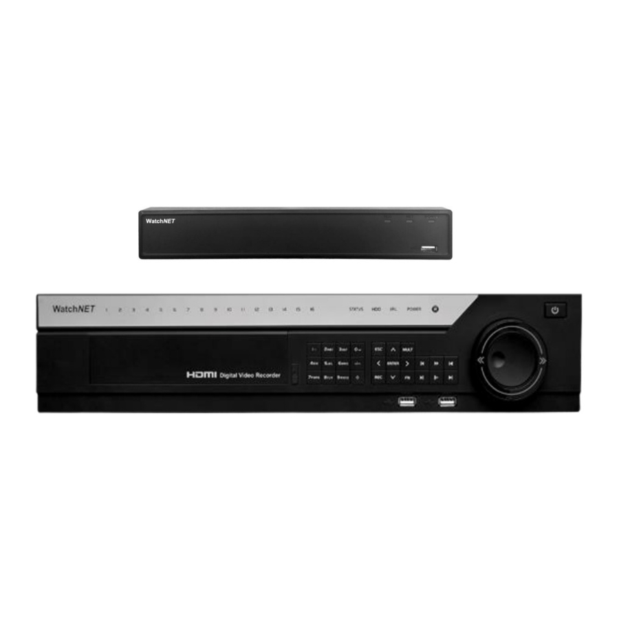
The Grand Tour This chapter introduces various components of the Device, remote control and mouse operations. 3.1 Front Panel 3.1.1 1U Figure 3-1 Table 3-1 Port Name Function Glows blue when HDD status is abnormal. Glows blue when network status is abnormal. POWER Glows blue when the power is connected properly. -
Page 12: Rear Panel
Port Name Function Glows blue when HDD status is abnormal. Glows blue when network status is abnormal. POWER Glows blue when the power is connected properly. Connects to peripheral devices such as USB storage device, USB port keyboard, and mouse. 3.2 Rear Panel 3.2.1 1U Figure 3-3... - Page 13 Port Name Function Audio output port Outputs audio signal to the devices such as the sound box. High definition audio and video signal output port. HDMI port The port outputs the uncompressed high definition video and multi-channel audio data to the connected display with HDMI port. Connects to the external devices such as keyboard, mouse, and USB port USB storage device.
- Page 14 Port Name Function Video output port Connects to video output devices such as TV. Video input port Connects to analog camera to input video signal. Four groups of alarm input ports (Group 1: port 1 to port 4; Group 2: port 5 to port 8; Group 3: port 9 to port 12; Group 4: port 13 to port 16).
- Page 15 Port Name Function External SATA port which connects to the device with SATA port. eSATA port Perform the jumper configuration when connecting HDD. 3.2.3 2U Figure 3-5 Table 3-5 Port Name Function Outputs the analog audio signal to the devices such as the sound Audio output port box.
- Page 16 Port Name Function RS-485 You can connect to the control devices such as speed dome PTZ. communication RS-485_A port is connected by the cable A and RS-485_B is port connected to the cable B. Four-wire full- duplex RS-485 Four-wire full-duplex 485 port. T+ and T- is the output wire; R+ port (T+, T-, R+, and R- is the input wire.
-
Page 17: Remote Control Operations
3.3 Remote Control Operations The remote control is not our standard accessory and might not be included in the accessary bag. It is supplied dependent on the model you purchased. Figure 3-6 Name Function Power button Press this button to boot up or shut down the device. Press this button to input device serial number, so that you can Address control the Device. -
Page 18: Mouse Operations
Name Function Go back to previous menu or cancel current operation (close front Esc. interface or control). Start or stop record manually. ⚫ In record interface, use the direction buttons to select the ⚫ Record channel that you want to record. Press this button for at least 1.5 seconds, and the manual ⚫... - Page 19 Operation Function Password input dialogue box pops up if you have not logged in yet. In live view window interface, you can go to the main menu. When you have selected one menu item, click it to view menu content. Implement the control operation.
-
Page 20: Connecting Basics
Connecting Basics This chapter introduces the typical connection diagrams and ports connections. 4.1 Typical Connection Diagram The following figure is for reference only. The actual product shall govern. Figure 4-1... -
Page 21: Connecting To Video And Audio Input And Output
4.2 Connecting to Video and Audio Input and Output 4.2.1 Video Input The video input interface is BNC. The input video format includes: PAL/NTSC BNC (1.0V 75Ω). The video signal should comply with your national standards. The input video signal shall have high SNR, low distortion; low interference, natural color, and suitable lightness. -
Page 22: Audio Output
Due to high impedance of audio input, please use active sound pick-up. Audio transmission is similar to video transmission. Try to avoid interference, dry joint, loose contact and it shall be away from high tension current. 4.2.4 Audio Output The audio output signal parameter is usually over 200mv 1KΩ (BNC or RCA). It can directly connect to low impedance earphone, active sound box or amplifier-drive audio output device. -
Page 23: Introducing Alarm Port
4.3.1 Introducing Alarm Port The alarm input ports are dependent on the model you purchased. Figure 4-2 Table 4-1 Icon Description 1,2,3,4,5,6, 7, 8, 9, 10, 11, 12, ALARM 1 to ALARM 16. The alarm becomes active in low voltage. 13,14,15,16 NO1 C1, NO2 C2, There are four groups of normally open activation output (on/off button). -
Page 24: Alarm Output
Figure 4-3 4.3.3 Alarm Output Provide external power to external alarm device. ⚫ To avoid overloading, read the following relay parameters table carefully. ⚫ RS-485 A/B cable is for the A/B cable of the PTZ decoder. ⚫ 4.3.4 Alarm Output Relay Parameters Refer to the actual product for relay model information. -
Page 25: Connecting To Rs-485 Port
4.4 Connecting to RS-485 Port Step 1 Connect the RS-485 cable of the PTZ camera to the RS-485 port on the Device. Ensure the match of A and B interfaces. Step 2 Connect the video out cable of the PTZ camera to the video input port on the Device. Step 3 Turn on the PTZ camera...
Need help?
Do you have a question about the PNT and is the answer not in the manual?
Questions and answers