Chapters
Table of Contents

Related Manuals for Tecno-gaz EkstraPLUS PT002TTM


Summary of Contents for Tecno-gaz EkstraPLUS PT002TTM
- Page 1 Art. PT002TTM Art. PT004TTM Istruzioni per l’uso ITALIANO Instructions for use ENGLISH Mode d’emploi FRANÇAIS 0TTMI0003 Bedienungsanleitung DEUTSCH 26.09.2013 Instrucciones de uso ESPAÑOL...
- Page 2 Questo apparecchio assolve ai criteri di conformità CE in quanto conforme alla direttiva 93/42/CEE. La dichiarazione di conformità originale è fornita in allegato al manuale. This device compliance to Directive 93/42/CE. The original declaration of confirmity is provided in attached to the manual. Cet appareil est conforme aux prescriptions CE puisque il respecte la instruction 93/42/CEE.
- Page 3 ITALIANO INDICE IMPIEGO E DESTINAZIONE D’USO SICUREZZA DISPOSITIVI DI SICUREZZA SMALTIMENTO DATI TECNICI IMBALLO IMBALLAGGIO TRASPORTO STOCCAGGIO DOTAZIONE DESCRIZIONE DISPOSITIVO INSTALLAZIONE COLLEGAMENTI RIEMPIMENTO SERBATOIO DISINFETTANTE / DETERGENTE E LUBRIFICANTE FUNZIONAMENTO APERTURA E CHIUSURA SPORTELLO DESCRIZIONE DEL PANNELLO COMANDI DESCRIZIONE SOFTWARE DESCRIZIONE DEL MENÙ...
- Page 4 ITALIANO Avvertenze generali e informazioni al destinatario. Attenzione alle indicazione scritte in parte a questo simbolo. IMPIEGO E DESTINAZIONE D’USO EKSTRA PLUS è un’apparecchiatura destinata esclusivamente al Settore Odontoiatrico per la manutenzione delle turbine e dei manipoli dentali, secondo le indicazioni riportate nel seguente manuale che costituisce parte integrante del dispositivo.
- Page 5 ITALIANO SICUREZZA L’apparecchiatura deve essere utilizzata esclusivamente per la manutenzione di strumenti il cui costruttore dichiara compatibili con un sistema di manutenzione automatica ed in generale esclusivamente per gli usi previsti dal costruttore del dispositivo EKSTRA PLUS. L’apparecchio non deve essere utilizzato in atmosfera potenzialmente esplosiva. Posizionare l’apparecchio lontano da fonti di calore o di radiazioni elettromagnetiche.
- Page 6 ITALIANO Dispositivi di sicurezza L’apparecchiatura è fornita dei seguenti dispositivi di sicurezza: - Blocco elettromagnetico per evitare l’apertura del portello durante l’esecuzione del ciclo - Aspirazione dell’ aerosol in camera (Par.10) Smaltimento Questo prodotto è soggetto alla direttiva 2002/96/EC del Parlamento europeo e del Consiglio dell’Unione europea sui rifiuti di apparecchiature elettriche (RAEE).
- Page 7 ITALIANO DATI TECNICI Fig.1 Temperatura di lavoro +5°C ÷ +30°C Umidità relativa MAX a 30°C Dimensioni ingombro (L x H x P) [mm] 470x 510 x 370 mm Dimensioni imballo (L x H x P)[mm] 580 x 540 x 565 mm Ingombro con portello aperto (P)[mm] 600 mm Peso (a vuoto)
- Page 8 ITALIANO IMBALLO Non sollevare mai prendendo il dispositivo dal carter anteriore. Tale operazione errata potrebbe danneggiare l’apparecchiatura. Non utilizzare apparecchi che presentano danni evidenti dovuti al trasporto. L’imballo deve essere conservato per tutto il periodo di garanzia. Il fabbricante non accetta resi senza imballo originale.
- Page 9 ITALIANO Lubrificante consigliato (Vedi Par.14: Accessori) Detergente consigliato (Vedi Par .14: Accessori) TUBO ALIMENTAZIONE PNEUMATICA Utilizzare per l’installazione dell’alimentazione pneumatica Dotazione prevista 3 m. – Cod. CP01009 Fig.2 TUBO SCARICO ESTENSIBILE Utilizzare per l’installazione dello scarico sul retro del dispositivo Dotazione prevista 1pz.
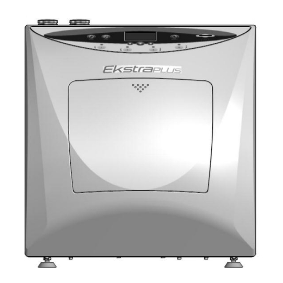
- Page 10 ITALIANO DESCRIZIONE DISPOSITIVO EKSTRA PLUS si presenta come un apparecchio per impiego da banco. La parte anteriore è eseguita in materiale termoplastico e la posteriore in lamiera verniciata. Display Plancia comandi Slot per SD Card Portello Fig.6 - Un pannello comandi posto frontalmente, mostra quattro pulsanti per la selezione delle postazioni, e sei per la gestione del processo;...
- Page 11 ITALIANO Postazioni turbine Postazioni manipoli Presa di compensazione vuoto Scarico camera Camera Fig.7 Nella parte superiore vi sono le bocche per il carico dei liquidi impiegati per il trattamento degli strumenti. Fig.8 Fig.9 Nella parte posteriore vi sono: - I rubinetti per lo svuotamento dei serbatoi che contengono i liquidi, - Lo scarico dei liquidi dal vano di trattamento, - Il connettore per l’alimentazione pneumatica, - Il connettore per l’alimentazione elettrica con portafusibili e interruttore.
- Page 12 ITALIANO INSTALLAZIONE L’installazione della macchina deve essere effettuata da personale autorizzato L’apparecchio non deve essere utilizzato in atmosfera potenzialmente esplosiva. L’apparecchio deve essere posizionato lontano da fonti di calore o di radiazioni elettromagnetiche. L’impianto elettrico deve essere conforme alla normativa vigente, verificare che l’impianto sia adeguato alle caratteristiche del dispositivo.
- Page 13 ITALIANO Disporre la macchina su di un banco avente altezza massima, perfettamente orizzontale. Posizionare dispositivo modo tale permettere all’operatore di ispezionare e pulire agevolmente il dispositivo; l’operatore deve poter accedere al retro del dispositivo Posizionare su una superficie perfettamente orizzontale, stabile e resistente a carichi di almeno 80 kg.
- Page 14 ITALIANO Collegamenti La posizione dei cavi e dei tubi non deve creare pericolo di inciampo per l’operatore e il personale. Controllare l’integrità del cavo di alimentazione. 1) Inserire la spina di alimentazione (Fig.12); inserire l’altro capo in una presa di corrente avente le seguenti caratteristiche: Tensione monofase 230V + terra Frequenza 50 Hz.
- Page 15 ITALIANO 3) Collegare il condotto di evacuazione dei fluidi esausti al portagomma girevole dello scarico del dispositivo (Fig.13). Collegare l’altra estremità allo scarico fognario assicurandosi della tenuta dell’imboccatura con il condotto stesso (Fig.14). Fig.14 Fig.13 Il dispositivo scarica per caduta, il tubo di scarico, deve scendere rispetto alla macchina. Evitare che il tubo di scarico presenti delle curve verso l’alto (sifoni) (Fig.14), o che generino ristagni.
- Page 16 ITALIANO ASSICURARSI CHE I RUBINETTI DI SCARICA SERBATOI (Fig.9) SIANO CHIUSI ACCENDERE SEMPRE LA MACCHINA PRIMA DI CARICARE I SERBATOI Durante il riempimento il dispositivo deve essere acceso e visualizzare la successiva opzione: ‘SELEZIONE CICLO’ (Par. 7.3 Video B). Detergente Sollevare il tappo relativo al liquido da ripristinare;...
- Page 17 ITALIANO - L’apertura dello sportello avviene premendo sulla parte centrale superiore dello stesso (come per la chiusura) fino ad ottenere lo scatto della serratura; togliendo pressione, lo sportello ruota verso il basso autonomamente per effetto delle molle di richiamo (Fig.17b; Fig.17a ). ...
- Page 18 ITALIANO Descrizione software Ogni area del display visualizza figure e/o descrizioni che rappresentano lo stato della macchina durante il processo, oppure scritte con le quali l’utente sceglie o imposta le varie funzioni disponibili. Azionando l’interruttore generale, posto nel retro della macchina, Fig.15 la macchina viene alimentata elettricamente e compare sul display, per pochi secondi, il “Video A“...
- Page 19 ITALIANO Descrizione del menù La struttura del menù è rappresentata nella sequenza dei video nella figura sottostante. Come precedentemente detto, per accedere al menù, bisogna premere il pulsante sottostante la scritta “MENÙ” che compare solo nel video B . Il display visualizza il video “C” nel quale sono disponibili QUATTRO opzioni: 1) Impostazione della lingua desiderata 2) Impostazione della data e ora 3) Impostazione della durata disinfezione...
- Page 20 ITALIANO IMPOSTAZIONE DELLA LINGUA Dal video C, portando il cursore in corrispondenza della scritta “LINGUA” e confermando con “OK”, viene visualizzato il video L. Con il comando “GIU’” si richiamano tutte le lingue disponibili, ITALIANO, FRANCESE, TEDESCO, INGLESE, SPAGNOLO. Individuata la lingua voluta, con il comando “OK” si conferma.
- Page 21 ITALIANO Individuato il giorno, con “OK” si conferma e compare il video D2 . Con il pulsante “AVANTI” si sposta la sottolineatura in corrispondenza del mese, video D3 Con il comando OK compare il video D4 , la sottolineatura lampeggia. Con il comando “SU”...
- Page 22 ITALIANO Per modificare l’ora bisogna spostare la sottolineatura, con il comando “AVANTI”, in corrispondenza dell’ora. Con la stessa modalità della data si imposta l’ora e i minuti . In qualsiasi punto della modifica , premendo il pulsante sottostante la scritta “ESCI”, le modifiche vengono salvate e si ritorna al video C “...
- Page 23 ITALIANO 5) IMPOSTAZIONE DATI DEL LABORATORIO l’utente può Come accennato, archiviare tutti cicli eseguiti memorizzati sulla SD card. Dati dispositivo Parte report testo personalizzabile computer dall’utente il quale ha la possibilità di inserire i dati dello studio o/e altro testo con annotazioni che ritiene utili: Creare/compilare file...
- Page 24 ITALIANO Tipologia e connessione strumenti All’interno della camera avviene il trattamento di manutenzione di manipoli e turbine. Essi devono essere connessi in maniera corretta agli appositi attacchi di seguito descritti. Postazioni TURBINE Guarnizione portello Postazioni MANIPOLI Scarico camera Fig.19 Pulsante rilascio MANIPOLO Incastro MANIPOLO O-Ring di delimitazione dei canali acqua/Spray...
- Page 25 ITALIANO Il dispositivo è in grado di ospitare: Postazioni 3 e 4 Postazioni 1 e 2 Turbina con adattatore rapido tipo MIDWEST Manipolo (ISO 9168 Type B/C) (Attacco ISO 3964 E-Type) ISO 9168 Type C ISO 9168 Type B Canalizzazioni: *+,&0*+1!&./-* 0*+1!&./-* 1) Acqua...
- Page 26 ITALIANO Visualizzazione durante il ciclo Come precedentemente detto dopo aver eseguito le operazioni di: Inserimento degli strumenti. Chiusura dello sportello. Selezione delle postazioni e tipo ciclo Si avvia il ciclo azionando il pulsante START. Poiché il trattamento, come precedentemente evidenziato nelle Fig.20 e Fig.22, avviene sulle singole tipologie di canali ...
- Page 27 ITALIANO CICLO DI LUBRIFICAZIONE: Il ciclo di lubrificazione si svolge secondo le seguenti fasi: Errori: cause e rimedi Situazioni che si possono verificare prima del funzionamento e che impediscono l’inizio di un ciclo: CAUSE: Viene visualizzato quando l’utente preme “START” e il livello del detergente risulta insufficiente per eseguire un ciclo.
- Page 28 ITALIANO CAUSE: Viene visualizzato durante il riempimento del serbatoio quando il livello raggiunge il limite massimo, accompagnato da un segnale acustico. RIMEDI: Sospendere il riempimento e mettere il tappo alla bocca di carico del serbatoio. CAUSE: Azionando “START” senza inserire “SD” compare il video E105.
- Page 29 ITALIANO SICUREZZA DURANTE IL FUNZIONAMENTO Lo sportello chiuso consente l’avvio del ciclo. Lo sportello viene bloccato dal dispositivo di sicurezza con il comando di START e rimane bloccato fino a fine ciclo . L’apertura dello sportello durante il ciclo non è possibile. ...
- Page 30 ITALIANO MESSAGGI D’ALLARME CICLO La visualizzazione degli allarmi sopra sono guasti o difetti di funzionamento ai quali non sempre l’utente è in grado di porre rimedio: - Premere OK, ripristinare le condizioni di utilizzo e ripetere il ciclo. - Il ripresentarsi inspiegabile di questi allarmi suggerisce all’utente di contattare l’assistenza tecnica seguendo le indicazioni contenute nel Par.13.
- Page 31 - a fine ciclo - per interruzione del ciclo (Tasto STOP) - Per l’insorgere di un errore che interrompe il ciclo TECNO-GAZ NON È RESPONSABILE DEI DANNI PRODOTTI DALL’USO IMPROPRIO DELLA MACCHINA. FINE CICLO La fine del ciclo impostato è indicato da un segnale acustico e dalla scritta a video “CICLO FINITO”.
- Page 32 ITALIANO MANUTENZIONE MANUTENZIONE E 1) MANUTENZIONE ORDINARIA La macchina non necessita di particolari manutenzioni. I componenti più esposti all’usura ed allo sporco sono: a) la guarnizione dello sportello (Fig.19 Cod.1TTMA0072); b) Le guarnizioni degli attacchi manipoli (Fig.20 Cod.3MECM0017); La pulizia periodica della camera di trattamento e del mobile in generale, si può esegue utilizzando il detergente-disinfettante consigliato.
- Page 33 ITALIANO In caso si debba spedire in sede seguire le seguenti indicazioni obbligatorie: Utilizzare l’imballo originale, se questo non è più in Vostro possesso, utilizzare un imballo adeguato. La merce viaggia con rischio a carico del mittente. Spedire solo il dispositivo (non inserire alcun componente contenuto nel kit accessori).
- Page 34 ITALIANO ACCESSORI A richiesta è possibile avere adattatori rapidi per le turbine delle maggiori marche in modo da ottenere la maggiore flessibilità di funzionamento possibile dal dispositivo e i liquidi consigliati. Sirona B/F Cod. 3MEDQ0003 Multiflex (KaVo) Cod. 3MEDQ0004 Roto quick (W&H) Cod.
-
Page 35: Table Of Contents
ENGLISH TABLE OF CONTENTS APPLICATION AND INTENDED USE SAFETY SAFETY DEVICES DISPOSAL SPECIFICATIONS PACKAGING PACKAGING TRANSPORT STORAGE SUPPLY DESCRIPTION OF THE DEVICE INSTALLATION CONNECTIONS FILLING THE DISINFECTANT/DETERGENT AND LUBRICANT TANKS OPERATION OPENING AND CLOSING THE DOOR DESCRIPTION OF THE CONTROL PANEL DESCRIPTION OF THE SOFTWARE DESCRIPTION OF THE MENU CONNECTION AND TYPE OF INSTRUMENTS... -
Page 36: Application And Intended Use
ENGLISH General instructions and information for the recipient. Pay attention to the indications on the side of this symbol. APPLICATION AND INTENDED USE EKSTRA PLUS is a unit intended exclusively for the Dental Industry for the maintenance of dental handpieces and turbines, according to the instructions in this manual, which forms an integral part of the device. -
Page 37: Safety
ENGLISH SAFETY The unit must only be used to perform maintenance on instruments whose manufacturer declares them to be compatible with an automatic maintenance system and from a general aspect, solely for the uses intended by the manufacturer of the EKSTRA PLUS device. The device must not be used in potentially explosive atmospheres. -
Page 38: Safety Devices
ENGLISH Safety devices The unit is supplied with the following safety devices: - Electromagnetic lock to prevent the door from being opened during the cycle. - Chamber aerosol suction (Para. 10). Disposal This product is subject to Directive 2002/96/EC of the European Parliament and of the Council of the European Union on waste electrical equipment (WEEE). -
Page 39: Specifications
ENGLISH SPECIFICATIONS Fig. 1 Operating temperature +5°C to +30°C MAX Relative humidity at 30°C Overall dimensions (L x H x P) [mm] 470 x 510 x 370 mm Packaging dimensions (L x H x P)[mm] 580 x 540 x 565 mm Dimensions with door open (P)[mm] 600 mm Weight (empty) -
Page 40: Packaging
ENGLISH PACKAGING Never lift the device from the front guard. This incorrect operation could damage the unit. Do not use devices that have been visibly damaged during transport. The packaging must be kept throughout the warranty period. The manufacturer does not accept returns without the original packaging. - Page 41 ENGLISH Recommended lubricant ( See par. 15. Accessories) Recommended detergent (See par. 15. Accessories) PNEUMATIC SUPPLY PIPE Use to install the pneumatic supply Supply provided 3 m – Code CP01009 Fig. 2 EXTENDABLE DRAIN PIPE Use to install the drain at the back of the device Supply provided 1 pc –...
-
Page 42: Description Of The Device
ENGLISH DESCRIPTION OF THE DEVICE EKSTRA PLUS comes as a device that is to be used on a counter. The front part is made of thermoplastic material and the rear in painted sheet metal. Display Control panel Slot for SD Card Door Fig. - Page 43 ENGLISH Turbine stations Handpiece stations Vacuum Chamber drain compensation intake Chamber Fig. 7 There are nozzles in the upper part for loading the liquid used for the treatment of the instruments. Detergent filler inlet Oil filler inlet Compressed air inlet Chamber drain Detergent tank drain valve...
-
Page 44: Installation
ENGLISH INSTALLATION The machine must be installed by authorised personnel The device must not be used in potentially explosive atmospheres. The device must be placed away from sources of heat or electromagnetic radiation. The electrical system must comply with regulations in force. Verify that the system is adequate for the characteristics of the device. - Page 45 ENGLISH Place the machine on a counter that is at least 90 cm high and perfectly level. Place the device so as to allow the operator to easily inspect and clean the device. The operator must be able to access the back of the device Place perfectly...
-
Page 46: Connections
ENGLISH Connections The position of the cables and pipes must not pose a tripping hazard for the operator and the personnel. Check the integrity of the power cord. 1) Insert the power supply pin (Fig. 12); insert the other end into a socket with the following characteristics: 230V single phase + earth Frequency 50 Hz... -
Page 47: Filling The Disinfectant/Detergent And Lubricant Tanks
ENGLISH 3) Connect the spent fluid drain pipe to the swivel hose connection of the drain of the device (Fig. 13). Connect the other end to the sewage drain, making sure the inlet of the pipe is sealed well (Fig. 14). Fig.14 Fig.13 The device drains by gravity and therefore, the drain pipe must descend with respect to the... -
Page 48: Operation
ENGLISH ALWAYS SWITCH THE MACHINE ON BEFORE FILLING THE TANKS MAKE SURE THE TANK DRAIN VALVES (Fig. 9) ARE CLOSED. The device must be switched for the filling operations and the next option must be displayed: ‘CYCLE SELECTION (Para. 7.3 Screen B). Detergent Lift the cap of the liquid that is to be topped-up;... -
Page 49: Description Of The Control Panel
ENGLISH - The door is opened by pressing the upper middle part of it (the same area that is pressed to close it) until the lock snaps; once the door is let go, it pivots downwards autonomously thanks to the return springs (Fig. -
Page 50: Description Of The Software
ENGLISH Description of the software Each area of the display shows figures and/or descriptions that represent the condition of the machine during the process, or messages with which the user chooses or sets the various functions available. Operate the main switch at the back of the machine (Fig. -
Page 51: Description Of The Menu
ENGLISH Description of the menu The menu structure is shown in the screen sequence in the figure below. SELECT LANGUAGE ENGLISH EXIT SCREEN A SCREEN L SCREEN C - OK DD-MM-AA hh-mm DATE TYPE OF CYCLE: 09 / 01 / 00 COMPLETE TIME SELECT STATIONS &... - Page 52 ENGLISH SETTING THE LANGUAGE MENU LANGUAGE When in screen C, move the cursor to LANGUAGE and press OK to confirm for screen L to be DATE - TIME displayed. DISINFECTION DURATION EXIT SCREEN C SCREEN B - MENU Use the DOWN command to retrieve all the languages available: ITALIAN, FRENCH, GERMAN, SELECT ENGLISH and SPANISH.
- Page 53 ENGLISH DATE 23 / 01 / 00 Once the correct day is identified, press OK to TIME confirm and screen D2 appears. 03:29 EXIT SCREEN D2 SCREEN D1 - OK DATE 23 / 01 / 00 The month will be underlined, as shown in TIME screen D3, when the NEXT button is pressed.
- Page 54 ENGLISH DATE 09 / 12 / 13 The time is changed by moving the underlining to the hour with the NEXT command. TIME 03:29 The hour and minutes are set in the same way as the date. EXIT SCREEN D7 SCREEN D6 - OK Press the button below EXIT at any point while modifying the data and the changes are saved before returning to MENU in screen C (Para.
- Page 55 ENGLISH LABORATORY DATA SETTINGS As mentioned, the user can store all the cycles performed on the SD card. Device data VERSION : xxx Part of the customised text report CLINIC:xxxxxxxxx on the user's computer. The user can ADDRESS:xxxxxxx enter the clinic's data and/or other text POSTCODE:xxxxxxx with notes that are deemed relevant:...
-
Page 56: Connection And Type Of Instruments
ENGLISH Connection and type of instruments Maintenance is performed on handpieces and turbines inside the chamber. They must be connected correctly as described below. TURBINE stations Door gasket HANDPIECE stations Chamber drain Fig. 19 HANDPIECE release button HANDPIECE interlock Defining O-ring of the Spray/water channels Fig. - Page 57 ENGLISH The device can host: Stations 3 and 4 Stations 1 and 2 Turbine with MIDWEST-type quick adapter Handpiece (ISO 9168 Type B/C) (ISO 3964 E-Type coupling) ISO 9168 Type C ISO 9168 Type B Channels: *+,&0*+1!&./-* 0*+1!&./-* 1) Water 2) Actuating air 3) Spray air 4) Drain...
-
Page 58: Display During The Cycle
ENGLISH Display during the cycle As previously mentioned, after performing the following steps: Inserting the instruments Closing the door Selecting the stations and type of cycle The cycle is launched by pressing the START button. Since the treatment, as previously shown in Fig.20 and Fig.22, is applied to individual channel types ... -
Page 59: Errors: Causes And Solutions
ENGLISH LUBRICATION CYCLE: The lubrication cycle is performed according to the following steps: DD-MM-AA hh-mm DD-MM-AA hh-mm TYPE OF CYCLE: TYPE OF CYCLE: LUBRICATION LUBRICATION PHASE 1 BLEED PHASE 2 LUBRICATION SCREEN B2-1 SCREEN B2-2 DD-MM-AA hh-mm DD-MM-AA hh-mm TYPE OF CYCLE: TYPE OF CYCLE: LUBRICATION LUBRICATION... - Page 60 ENGLISH FULL OIL TANK CAUSES: This is displayed when the level reaches the maximum limit while filling tank, accompanied by a beep. FLASHES SOLUTIONS: Suspend the filling operations and put the cap on the filler inlet of the tank. SCREEN E104 CAUSES: Screen E105 appears if START is pressed and SD NOT INSERTED...
-
Page 61: Safety During Operation
ENGLISH SAFETY DURING OPERATION The cycle can be launched if the door is closed. The door is locked by the safety device upon the START command and remains blocked until the cycle is completed. The door cannot be opened during the cycle. ... -
Page 62: Cycle Alarm Messages
ENGLISH CYCLE ALARM MESSAGES ALARM 201 ALARM 202 ALARM 203 LOW AIR PRESSURE STATION 1 STATION 2 SCREEN A1 LESS THAN 4 BAR SCREEN A2 DISPENS. DETERGENT SCREEN A3 DISPENS. DETERGENT ALARM 204 ALARM 205 ALARM 206 STATION 3 STATION 4 STATION 1 SCREEN A4 DISPENS. -
Page 63: Emission Of Harmful Substances
- at the end of the cycle - if the cycle is interrupted (STOP button) - if an error occurs that interrupts the cycle TECNO-GAZ CANNOT BE HELD LIABLE FOR ANY DAMAGE DERIVING FROM IMPROPER USE OF THE MACHINE. END OF CYCLE The set end of cycle is indicated by a beep and FINISHED CYCLE appearing on the screen. -
Page 64: Maintenance
ENGLISH MAINTENANCE MAINTENANCE AND 1) ROUTINE MAINTENANCE The machine does not require any special maintenance. The components that are most exposed to wear and dirt are: a) the seal of the door (Fig. 19 Code 1TTMA0072); b) The seals of the handpiece couplings (Fig. 20 Code 3MECM0017); The recommended disinfectant can be used for the periodic cleaning of the maintenance chamber and the cabinet in general. - Page 65 ENGLISH The following steps are mandatory if the machine must be shipped to the company: Use the original packaging. If you no longer have this, use adequate packaging. The transportation risks are borne by the sender. Send only the device (do not put any component of the accessory kit). Thoroughly clean the chamber and the entire device before sending it.
-
Page 66: Accessories
ENGLISH ACCESSORIES Turbine quick adapters of major brands can be requested in order to obtain greater operation flexibility of the device and the recommended liquids. Sirona B Code 3MEDQ0003 Multiflex (KaVo) Code 3MEDQ0004 Roto quick (W&H) Code 3MEDQ0002 Unifix (Bien Air) Code 3MEDQ0005 MachLite/Platelus (NSK) Code 3MEDQ0001... - Page 67 FRANÇAIS INDEX EMPLOI ET DOMAINE D'UTILISATION SÉCURITÉ DISPOSITIFS DE SÉCURITÉ ÉLIMINATION DONNÉES TECHNIQUES EMBALLAGE EMBALLAGE TRANSPORT STOCKAGE ÉQUIPEMENT DESCRIPTION DISPOSITIF INSTALLATION RACCORDEMENTS REMPLISSAGE DU RÉSERVOIR DÉSINFECTANT / DÉTERGENT ET LUBRIFIANT FONCTIONNEMENT OUVERTURE ET FERMETURE PORTE DESCRIPTION DU PANNEAU DE COMMANDES DESCRIPTION DU LOGICIEL DESCRIPTION DU MENU TYPE ET CONNEXION DES INSTRUMENTS...
- Page 68 FRANÇAIS Recommandations générales et informations au destinataire. Attention aux indications inscrites à côté de ce symbole. EMPLOI ET DOMAINE D'UTILISATION EKSTRA PLUS est un dispositif destiné exclusivement au Secteur Dentaire pour la maintenance des turbines et des poignées dentaires, conformément aux indications reportées dans le manuel suivant, lequel constitue une partie intégrante du dispositif.
- Page 69 FRANÇAIS SÉCURITÉ Le dispositif doit être utilisé uniquement pour la maintenance des instruments dont le fabricant déclare les compatibilités avec un système de maintenance automatique et, en général, uniquement pour les utilisations prévues par le fabricant du dispositif EKSTRA PLUS. L'appareil ne doit pas être utilisé...
- Page 70 FRANÇAIS Dispositifs de sécurité L'appareil est équipé des dispositifs de sécurité suivants: - Blocage électromagnétique pour empêcher l'ouverture de la porte durant l'exécution du cycle. - Aspiration de l'aérosol dans la chambre (Par.10). Élimination Ce produit est soumis à la directive 2002/96/EC du Parlement européen et du Conseil de l'Union européenne sur les déchets des équipements électriques (DEEE).
- Page 71 FRANÇAIS DONNÉES TECHNIQUES Fig.1 Température de fonctionnement +5°C ÷ +30°C Humidité relative MAX à 30°C Dimensions (L x H x P) [mm] 470 x 510 x 370 mm Dimensions emballage (L x H x P)[mm] 580 x 540 x 565 mm Dimensions avec porte ouverte (P)[mm] 600 mm Poids (à...
- Page 72 FRANÇAIS EMBALLAGE Ne jamais soulever le dispositif en le prenant par le carter avant. Cette opération incorrecte pourrait endommager le dispositif. Ne pas utiliser les appareils qui présentent des dommages évidents dus au transport. L'emballage doit être conservé pendant toute la période de garantie. Le fabriquant n'accepte pas les appareils rendus sans leur emballage d'origine.
- Page 73 FRANÇAIS Lubrifiant recommandé (Voir: 14 Accessoires) Détergent recommandé (Voir : 14 Accessoires) TUYAU D'ALIMENTATION PNEUMATIQUE À utiliser pour l'installation de l'alimentation pneumatique Équipement prévu 3 m. – Code CP01009 Fig.2 TUBE D’ÉVACUATION EXTENSIBLE À utiliser pour l'installation de l'évacuation à l'arrière du dispositif Équipement prévu 1pc.
- Page 74 FRANÇAIS DESCRIPTION DU DISPOSITIF EKSTRA PLUS se présente comme un appareil pour un emploi sur paillasse. La partie antérieure est réalisée en matériau thermoplastique et celle postérieure en tôle vernie. Afficheur Tableau de commandes Fente pour insertion carte SD Porte Fig.6 - Un panneau de commandes, situé...
- Page 75 FRANÇAIS Emplacements Emplacements turbines poignées Prise de Évacuation compensation vide chambre Chambre Fig.7 Dans la partie supérieure, se trouvent les orifices pour le remplissage des liquides employés pour le traitement des instruments. Orifice de remplissage détergent Orifice de remplissage huile Entrée air comprimé...
- Page 76 FRANÇAIS INSTALLATION L'installation de la machine doit être effectuée par un personnel agréé L'appareil ne doit pas être utilisé dans une atmosphère potentiellement explosive. L'appareil doit être placé loin des sources de chaleur ou de radiations électromagnétiques. L'installation électrique doit être conforme à la réglementation en vigueur, vérifier que l’installation soit adaptée aux caractéristiques du dispositif.
- Page 77 FRANÇAIS Disposer la machine sur une table ayant hauteur maximum parfaitement horizontale. Positionner dispositif manière à permettre à l'opérateur d'inspecter et de nettoyer facilement le dispositif; l'opérateur doit pouvoir accéder à l'arrière du dispositif. Positionner sur une surface parfaitement horizontale, stable et résistante à...
- Page 78 FRANÇAIS Raccordements La position des câbles et des tuyaux ne doit générer de danger de chute pour l'opérateur et le personnel. Contrôler l'intégrité du câble d'alimentation. 1) Insérer la fiche d'alimentation (Fig.12); insérer l'autre tête dans une prise de courant ayant les caractéristiques suivantes: Tension monophasée 230V + terre Fréquence 50 Hz.
- Page 79 FRANÇAIS 3) Raccorder le conduit d'évacuation des fluides usés à l'embout pivotant de la vidange du dispositif (Fig.13). Raccorder l'autre extrémité à l'évacuation à l'égout, en s'assurant de l'étanchéité de l'orifice avec le conduit (Fig.14). Fig.14 Fig.13 Le dispositif évacue par écoulement gravitaire, le tuyau d'évacuation doit descendre par rapport à...
- Page 80 FRANÇAIS S'ASSURER QUE LES ROBINETS D’ÉVACUATION DES RÉSERVOIRS (Fig.9) SOIENT FERMÉS. TOUJOURS ALLUMER MACHINE AVANT REMPLIR RÉSERVOIRS Pendant le remplissage, le dispositif doit être allumé et afficher l'option suivante: 'SÉLECTION CYCLE' (Par. 7.3 Vidéo B). Détergent Soulever bouchon correspondant liquide à...
- Page 81 FRANÇAIS - L'ouverture de la porte s'effectue en appuyant sur la partie centrale supérieure de celle-ci (comme pour la fermeture) jusqu'à obtenir le déclic du verrou; en retirant la pression de la main, la porte pivote vers le bas indépendamment, sous l'effet des ressorts de rappel (Fig.17b; Fig.17a). ...
- Page 82 FRANÇAIS Description du logiciel Chaque zone de l'afficheur visualise des figures et/ou des descriptions qui représentent l'état de la machine durant le processus, ou bien des indications grâce auxquelles l'utilisateur choisit ou programme les différentes fonctions disponibles. En activant l'interrupteur général, situé à l'arrière de la machine, Fig.15, machine...
- Page 83 FRANÇAIS Description du menu La structure du menu est représentée dans la séquence des vidéos à la figure ci-dessous. SÉLECTIONNER LA LANGUE FRANÇAIS EXIT SORTIR VIDÉO A VIDÉO L VIDÉO C x OK DD-MM-AA hh-mm DATE TYPE DE CYCLE: 09 / 01 / 00 COMPLET HEURE SÉLECTIONNER EMPLACEMENTS...
- Page 84 FRANÇAIS CONFIGURATION DE LA LANGUE MENU LANGUE À partir de la vidéo C, en amenant le curseur à la DATE-HEURE hauteur de l'inscription "LANGUE" et en confirmant par "OK", la vidéo L s'affiche. DUREE DESINFECTION SORTIR VIDÉO C VIDÉO B x MENU Par la commande "BAS", on fait défiler toutes les SÉLECTIONNER langues disponibles, ITALIEN, FRANÇAIS,...
- Page 85 FRANÇAIS Après avoir choisi le jour, on confirme par "OK" DATE et la vidéo D2 apparaît. 23 / 01 / 00 HEURE 03:29 SORTIR VIDÉO D2 VIDÉO D1 x OK DATE 23 / 01 / 00 Avec le bouton "SUIVANT", on déplace la mise HEURE en relief à...
- Page 86 FRANÇAIS Pour modifier l'heure, il faut déplacer la mise en DATE relief, avec la commande "SUIVANT", à la hauteur de l'heure. 09 / 12 / 13 Selon la même modalité que celle de la date, HEURE on configure l'heure et les minutes. 03:29 SORTIR VIDÉO D7...
- Page 87 FRANÇAIS CONFIGURATION DES DONNÉES DU LABORATOIRE Comme déjà mentionné, l'utilisateur peut archiver tous cycles exécutés, mémorisés sur la carte SD. VERSION : xxx Données du dispositif CABINET:xxxxxxxxx Partie du rapport personnalisable RUE:xxxxxxx sur l'ordinateur par l'utilisateur, lequel CODE POSTAL:xxxxxxx a la possibilité...
- Page 88 FRANÇAIS Type et connexion instruments À l'intérieur de la chambre, a lieu le traitement de maintenance des poignées et turbines. Celles-ci doivent être connectées de manière correcte aux raccords prévus à cet effet, qui sont décrits ci-dessous: Emplacements Joint porte TURBINES Emplacements POIGNÉES...
- Page 89 FRANÇAIS Le dispositif est en mesure de contenir: Emplacements 3 et 4 Emplacements 1 et 2 Turbine avec adaptateur rapide type MIDWEST Poignée (ISO 9168 Type B/C) (Raccord ISO 3964 E- Type) ISO 9168 Type C ISO 9168 Type B Canalisations: *+,&0*+1!&./-* 0*+1!&./-*...
- Page 90 FRANÇAIS Visualisation durant le cycle Comme mentionné précédemment, après avoir effectué les opérations de: Insertion des instruments. Fermeture de la porte. Sélection des emplacements et type de cycle On démarre le cycle en actionnant le bouton START. Poiché il trattamento, come precedentemente evidenziato nelle Fig.20 e Fig.22, avviene sulle singole tipologie di canali ...
- Page 91 FRANÇAIS CYCLE DE LUBRIFICATION: Le cycle de lubrification se déroule selon les phases suivantes: JJ-MM-AA hh-mm JJ-MM-AA hh-mm TYPE OF CYCLE: TYPE OF CYCLE: LUBRICATION LUBRICATION PHASE 1 BLEED PHASE 2 LUBRICATION VIDÉO B2-2 VIDÉO B2-1 JJ-MM-AA hh-mm JJ-MM-AA hh-mm TYPE OF CYCLE: TYPE OF CYCLE: LUBRICATION...
- Page 92 FRANÇAIS RÉSERVOIR HUILE PLEIN CAUSES: Est affiché pendant le remplissage du réservoir quand le niveau atteint la limite maximale, accompagné d'un signal acoustique. CLIGNOTE SOLUTIONS: Suspendre le remplissage et mettre le bouchon sur l'orifice d'évacuation du réservoir. VIDÉO E104 CAUSES: En actionnant "START", sans insérer "SD", SD PAS INSÉRÉE apparaît la vidéo E105.
- Page 93 FRANÇAIS SÉCURITÉ PENDANT LE FONCTIONNEMENT La porte fermée permet le démarrage du cycle. La porte est bloquée par le dispositif de sécurité par la commande du START et reste bloquée jusqu'à la fin du cycle. L'ouverture de la porte pendant le cycle n'est pas possible. ...
- Page 94 FRANÇAIS MESSAGES D'ALARME CYCLE ALARME 201 ALARME 202 ALARME 203 PRESSION AIR BASSE EMPLACEMENT 1 EMPLACEMENT 2 VIDÉO A1 INFÉRIEURE À 4 BARS VIDÉO A2 NETTOYAGE DÉTERGENT VIDÉO A3 NETTOYAGE DÉTERGENT ALARME 204 ALARME 205 ALARME 206 EMPLACEMENT 3 EMPLACEMENT 4 EMPLACEMENT 1 VIDÉO A4 NETTOYAGE DÉTERGENT...
- Page 95 - en fin de cycle - par l'interruption du cycle (Touche STOP) - par l'apparition d'une erreur qui interrompt le cycle TECNO-GAZ N'EST PAS RESPONSABLE DES DOMMAGES PROVOQUÉS PAR UNE UTILISATION IMPROPRE DE LA MACHINE. FIN DU CYCLE La fin du cycle programmé est indiqué par un signal acoustique et par l'affichage de l'inscription de "CYCLE ACHEVÉ".
- Page 96 FRANÇAIS MAINTENANCE MAINTENANCE ET 1) MAINTENANCE ORDINAIRE La machine ne nécessite pas de maintenance particulière. Les composants les plus exposés à l'usure et à la saleté sont: a) le joint de la porte (Fig.19 Code 1TTMA0072); b) les joints des raccords poignées (Fig.20 Code 3MECM0017); Le nettoyage régulier de la chambre de traitement et du meuble en général peut être effectué...
- Page 97 FRANÇAIS Si on doit le renvoyer en usine, suivre les indications obligatoires suivantes: Utilisez l'emballage d'origine, si celui-ci n'est plus en votre possession, utilisez un emballage approprié. Les risques liés au transport de la marchandise sont à charge de l'expéditeur. ...
- Page 98 FRANÇAIS ACCESSOIRES Sur demande, il est possible d'avoir des adaptateurs rapides pour les turbines des plus grandes marques de manière à obtenir la plus grande flexibilité de fonctionnement possible du dispositif et des liquides recommandés. Sirona B Code 3MEDQ0003 Multiflex (KaVo) Code 3MEDQ0004 Roto quick (W&H) Code 3MEDQ0002...
- Page 99 DEUTSCH INHALTSVERZEICHNIS ANWENDUNG UND ZWECKBESTIMMUNG SICHERHEIT SICHERHEITSVORRICHTUNGEN ENTSORGUNG TECHNISCHE DATEN VERPACKUNG VERPACKUNGSVERFAHREN TRANSPORT LAGERUNG AUSSTATTUNG BESCHREIBUNG DER VORRICHTUNG INSTALLATION ANSCHLÜSSE MIT DESINFEKTIONS-/ REINIGUNGS- UND SCHMIERMITTEL BEHÄLTERBEFÜLLUNG FUNKTIONSWEISE TÜRÖFFNUNG UND -SCHLIESSUNG BEDIENTAFELBESCHREIBUNG SOFTWAREBESCHREIBUNG MENÜBESCHREIBUNG INSTRUMENTENTYPOLOGIE UND -ANSCHLUSS ANZEIGE BEIM ZYKLUS FEHLER: URSACHEN UND ABHILFEN BETRIEBSSICHERHEIT ZYKLUS-ALARMMELDUNGEN 10.
-
Page 100: Anwendung Und Zweckbestimmung
DEUTSCH Allgemeine Hinweise und Informationen für den Empfänger. Beachten Sie die schriftlichen Angaben, die neben diesem Symbol abgebildet sind! ANWENDUNG UND ZWECKBESTIMMUNG EKSTRA PLUS ist ein Gerät, das ausschließlich dem Zahnärztlichen Bereich vorbehalten ist und der Instandhaltung der Dentalturbinen und -handstücke in Übereinstimmung mit den Anweisungen dient, die in dieser Anleitung angeführt sind. -
Page 101: Sicherheit
DEUTSCH SICHERHEIT Das Gerät ist ausschließlich für die Instandhaltung von Instrumenten einzusetzen, deren Kompatibilität mit einer automatischen Instandhaltung vom Hersteller ausdrücklich erklärt wurde. Das Gerät ist im Allgemeinen ausschließlich für die Einsätze zu verwenden, die vom Hersteller der Vorrichtung EKSTRA PLUS vorgesehen sind. Das Gerät darf nicht in einer explosionsgefährdeten Umgebung eingesetzt werden. -
Page 102: Sicherheitsvorrichtungen
DEUTSCH Sicherheitsvorrichtungen Das Gerät ist mit folgenden Sicherheitsvorrichtungen ausgestattet: - Elektromagnetische Sperre zur Vermeidung der Türöffnung während der Zyklusausführung - Aerosolansaugung in der Kammer (Abschn. 10) Entsorgung Dieses Produkt unterliegt der Richtlinie 2002/96/EC des Europäischen Parlaments und des Rats der Europäischen Union über Elektro- und Elektronikgeräte-Abfall (WEEE). -
Page 103: Technische Daten
DEUTSCH TECHNISCHE DATEN Abb.1 Betriebstemperatur +5°C ÷ +30°C MAX relative Feuchte bei 30°C Abmessungen (L x H x P) [mm] 470 x 510 x 370 mm Abmessungen Verpackung (L x H x P)[mm] 580 x 540 x 565 mm Abmessungen bei offener Tür (P)[mm] 600 mm Gewicht (leer) 24 kg... -
Page 104: Verpackung
DEUTSCH VERPACKUNG Die Vorrichtung niemals am vorderen Schutzgehäuse anheben. Dieser falsche Vorgang könnte das Gerät beschädigen. Keine Geräte verwenden, die offensichtliche Transportschäden aufweisen. Die Verpackung ist für die gesamte Garantiedauer aufzubewahren. Der Hersteller nimmt keine Rückgaben ohne Originalverpackung an. ... -
Page 105: Ausstattung
DEUTSCH KURZE BEDIENUNGSANLEITUNG: Ist in Maschinennähe aufzubewahren. Empfohlenes Schmiermittel (Siehe § 15 ZUBEHÖR) Empfohlenes Reinigungsmittel (Siehe § 15 ZUBEHÖR) DRUCKLUFTSCHLAUCH Für die Installation der Druckluftversorgung verwenden. Vorgesehene Ausstattung 3 m. – Code CP01009 Abb.2 VERLÄNGERBARER ABFLUSSSCHLAUCH Für die Installation des Abflusses auf der Rückseite der Vorrichtung verwenden. Vorgesehene Ausstattung 1St. -
Page 106: Beschreibung Der Vorrichtung
DEUTSCH BESCHREIBUNG DER VORRICHTUNG EKSTRA PLUS präsentiert sich in Form eines Tischgeräts. Der Frontteil ist aus thermoplastischem Material, der rückseitige Teil aus lackiertem Aluminium. Display Schalttafel Steckplatz für SD- Karte Tür Abb.6 - Eine Bedientafel auf der Vorderseite zeigt vier Druckknöpfe für die Auswahl der Positionen und sechs für die Prozesssteuerung auf;... - Page 107 DEUTSCH Position der Position der Turbinen Handstücke Öffnung für Vakuumkompensation Kammerabfluss Kammer Abb.7 Im oberen Teil befinden sich die Öffnungen für die Ladung der Flüssigkeiten, die für die Instrumentenbehandlung verwendet werden. Ladeöffnung Reinigungsmittel Ladeöffnung Öl Eingang Druckluft Ablasshahn Kammerabfluss Reinigungsmittelbehälter - Steckdose Ablasshahn - Sicherungsträger...
-
Page 108: Installation
DEUTSCH INSTALLATION Die Installation der Maschine ist ausschließlich Aufgabe des dazu berechtigten Personals Das Gerät darf nicht in einer explosionsgefährdeten Umgebung eingesetzt werden. Das Gerät ist fern von Wärmequellen oder elektromagnetischen Strahlungen aufzustellen. Die Elektroanlage hat den geltenden Vorschriften zu entsprechen. Sicherstellen, dass die Anlage sich für die Eigenschaften der Vorrichtung eignet. - Page 109 DEUTSCH Maschine einen hundertprozentig waagerechten Tisch stellen, dessen Maximalhöhe 90 cm beträgt. Vorrichtung aufzustellen, dass der Bediener mühelos prüfen reinigen kann; der Bediener muss auf die Rückseite der Vorrichtung Zugriff haben. Vorrichtung eine hundertprozentig waagerechte und stabile Fläche stellen, die einer Belastung mindestens 80 kg standhält.
-
Page 110: Anschlüsse
DEUTSCH Anschlüsse Die Anordnung der Kabel und Schläuche darf keine Stolpergefahr für den Bediener und das Personal darstellen. Stromkabel auf seinen einwandfreien Zustand prüfen. 1) Den Netzstecker einführen (Abb.12); das andere Ende in eine Steckdose stecken, die nachstehende Eigenschaften aufweist: Einphasenspannung 230V + Erde Frequenz 50 Hz. -
Page 111: Behälterbefüllung Mit Desinfektions-/ Reinigungs- Und Schmiermittel
DEUTSCH 3) Den Ablasskanal der verbrauchten Flüssigkeiten an den drehbaren Schlauchhalter des Abflusses der Vorrichtung anschließen (Abb.13). Das andere Ende an den Ablass der Kanalisation anschließen und die Dichtigkeit der Tülle am Kanal sicherstellen (Abb.14). Fig.14 Fig.13 Die Vorrichtung leitet durch Gefälle ab und hat gegenüber der Maschine abzufallen. Vermeiden Sie am Abflussschlauch nach oben zeigende Bögen (Siphons) (Abb.14). -
Page 112: Funktionsweise
DEUTSCH VOR DER BEHÄLTERBEFÜLLUNG ZUERST DIE MASCHINE EINSCHALTEN SICHERSTELLEN, DASS ABFLUSSHÄHNE BEHÄLTER (Abb.9) GESCHLOSSEN SIND. Bei der Befüllung hat die Vorrichtung eingeschaltet zu sein und die darauf folgende Option anzuzeigen: ‘ZYKLUSWAHL (Abschn. 7.3 Seite B). Reinigungsmittel Den Stöpsel anheben, der sich auf die zu füllende Flüssigkeit bezieht. -
Page 113: Bedientafelbeschreibung
DEUTSCH - Die Türöffnung erfolgt durch Druckausübung auf den oberen Mittelbereich der Tür (wie beim Schließen), bis das Schloss schnappt; wird kein Druck mehr ausgeübt, rotiert die Tür wegen der Rückstellfeder von allein nach unten (Abb.17b; Abb.17a). Während des Zyklus kann die Tür nicht geöffnet werden; sie ist gesperrt und kann nur am Zyklusende oder durch Betätigung des STOPP-Steuerbefehls entsperrt werden. -
Page 114: Softwarebeschreibung
DEUTSCH Softwarebeschreibung Jeder Displaybereich zeigt Figuren bzw. Beschreibungen, die den Maschinenzustand während des Prozesses darstellen, oder Schriften, anhand derer der Bediener die zur Verfügung stehenden Funktionen wählt oder einstellt. Durch Betätigung des Hauptschalters hinter der Maschine, Abb.15, wird die Maschine mit Strom versorgt und auf dem Display erscheint für wenige Sekunden die "Seite A", die das Herstellerlogo und die geladene Softwareversion anzeigt. -
Page 115: Menübeschreibung
DEUTSCH Menübeschreibung Der Menüaufbau ist in der Abfolge der Bildschirmseiten in der Abbildung unten dargestellt. SPRACHE AUSWÄHLEN DEUTSCH BEENDEN SEITE A SEITE L SEITE C x OK TT-MM-JJ hh-mm DATE ZYKLUSART: 09 / 01 / 00 KOMPLETT TIME POSITIONEN UND ZYKLUS WÄHLEN, 03:29 START DRÜCKEN MENÜ... - Page 116 DEUTSCH EINSTELLUNG DER SPRACHE MENÜ SPRACHE Auf der Seite C ist der Cursor auf die Schrift "SPRACHE" zu setzen und der Vorgang mit "OK" DATUM-UHRZEIT zu bestätigen. Nun erscheint die Seite L. DAUER DER DESINFEKTION BEENDEN SEITE C SEITE B x MENÜ Mit dem Steuerbefehl "RUNTER"...
- Page 117 DEUTSCH Wurde der Tag ermittelt, ist dieser mit "OK" zu DATUM bestätigen und die Bildschirmseite D2 23 / 01 / 00 erscheint. UHRZEIT 03:29 BEENDEN SEITE D2 SEITE D1 x OK DATUM 23 / 01 / 00 Mit der Schaltfläche "VOR" wird die UHRZEIT Unterstreichung auf den Monat verschoben, Seite D3.
- Page 118 DEUTSCH Zur Abänderung der Uhrzeit ist die DATUM Unterstreichung mit dem Steuerbefehl "VOR" auf die Uhrzeit zu verschieben. 09 / 12 / 13 Die Einstellung der Uhrzeit und Minuten erfolgt UHRZEIT genau wie beim Datum. 03:29 BEENDEN SEITE D7 SEITE D6 x OK Die Änderungen können jederzeit während dieses Ablaufes gespeichert werden: Hierzu den Druckknopf unter der Schrift "BEENDEN"...
- Page 119 DEUTSCH 5) EINSTELLUNG DER LABORDATEN Der Bediener kann, wie bereits erwähnt, alle ausgeführten und gespeicherten Zyklen auf der SD-Karte archivieren. Daten der Vorrichtung UNTERSUCHUNG:xxxxxxxxx Teil des im PC kundenspezifisch STRASSE:xxxxxxx gestaltbaren Textberichts; PLZ:xxxxxxx Bediener kann Daten STADT: xxxxxx Untersuchung bzw.
-
Page 120: Instrumententypologie Und -Anschluss
DEUTSCH Instrumententypologie und -anschluss Die Behandlung und Instandhaltung der Turbinen und Handstücke erfolgt im Kammerninnern. Die Instrumente sind an die jeweiligen, nachstehend beschriebenen Anschlüsse korrekt anzuschließen. Positionen Türdichtung TURBINEN Positionen HANDSTÜCKE Kammerabfluss Abb.19 Entsperrtaste HANDSTÜCK Steckverbindung HANDSTÜCK Runddichtring zur Begrenzung der Wasser-/Spraykanäle Schraubverbindung für Schnellanschluss TURBINE... - Page 121 DEUTSCH Die Vorrichtung kann Folgendes aufnehmen: Positionen 3 und 4 Positionen 1 und 2 Turbine mit Schnelladapter Typ MIDWEST Handstück (ISO 9168 Type B/C) (Anschluss ISO 3964 E- Type) ISO 9168 Type C ISO 9168 Type B Kanalisationen: *+,&0*+1!&./-* 0*+1!&./-* 1) Wasser 2) Betätigungsluft 3) Sprayluft...
-
Page 122: Anzeige Beim Zyklus
DEUTSCH Anzeige beim Zyklus Wie zuvor beschrieben wird nach der Einschaltung der Instrumente der Schließung der Tür der Auswahl der Positionen und der Zyklustypologie der Zyklus durch Betätigung der Drucktaste START aktiviert. Die Behandlung erfolgt, wie bereits in den Abb. 20 und 22 gezeigt, für die verschiedenen Arten von Kanälen. -
Page 123: Fehler: Ursachen Und Abhilfen
DEUTSCH SCHMIERZYKLUS: Der Schmierzyklus erfolgt gemäß nachstehenden Phasen: TT-MM-JJ hh-mm TT-MM-JJ hh-mm ZYKLUSART: ZYKLUSART: SCHMIERUNG SCHMIERUNG PHASE 1 SÄUBERUNG PHASE 2 SCHMIERUNG SEITE B2-1 SEITE B2-2 TT-MM-JJ hh-mm TT-MM-JJ hh-mm ZYKLUSART: ZYKLUSART: SCHMIERUNG SCHMIERUNG ZYKLUS ZU ENDE PHASE 3 SCHMIERUNG SEITE B2-4 SEITE B2-3 Fehler: Ursachen und Abhilfen... - Page 124 DEUTSCH URSACHEN: ÖLBEHÄLTER VOLL Erscheint, wenn bei der Behälterfüllung der maximale Füllstand erreicht wird. Es ist auch ein akustisches Signal zu hören. BLINKT ABHILFEN: Befüllung unterbrechen Ladeöffnung des Behälters mit dem Stöpsel SEITE E104 verschließen. URSACHEN: Bei Betätigung von "START" ohne das Einfügen "SD"erscheint SD NICHT EINGESTECKT...
-
Page 125: Betriebssicherheit
DEUTSCH BETRIEBSSICHERHEIT Die geschlossene Tür ermöglicht die Zykluseinschaltung. Die Tür wird mit dem Steuerbefehl START durch die Sicherheitsvorrichtung gesperrt und bleibt bis zum Zyklusende in diesem Zustand. Eine Türöffnung ist während des Zyklus nicht möglich. Durch Betätigung von START beginnt der Zyklus von vorne. ... -
Page 126: Zyklus-Alarmmeldungen
DEUTSCH ZYKLUS-ALARMMELDUNGEN ALARM 201 ALARM 202 ALARM 203 LUFTDRUCK NIEDRIG POSITION 1 POSITION 2 SEITE A1 UNTER 4 BAR SEITE A2 REINIGUNGSMITTELABGABE SEITE A3 REINIGUNGSMITTELABGABE ALARM 204 ALARM 205 ALARM 206 POSITION 3 POSITION 4 POSITION 1 SEITE A4 REINIGUNGSMITTELABGABE SEITE A5 REINIGUNGSMITTELABGABE SEITE A6... -
Page 127: Freisetzung Von Schadstoffen
- am Ende des Zyklus - bei einer Zyklusunterbrechung (STOPP-Taste) - bei Auftreten eines Fehlers, der den Zyklus unterbricht TECNO-GAZ HAFTET NICHT FÜR SCHÄDEN, DIE AUF EINEN UNSACHGEMÄSSEN MASCHINENGEBRAUCH ZURÜCKZUFÜHREN SIND. ZYKLUSENDE Das eingestellte Zyklusende wird durch ein akustisches Signal und die Bildschirmschrift "ZYKLUS ZU ENDE" angezeigt. -
Page 128: Instandhaltung
DEUTSCH INSTANDHALTUNG INSTANDHALTUNG UND 1) ORDENTLICHE INSTANDHALTUNG Die Maschine benötigt keine besonderen Instandhaltungseingriffe. Die Komponenten, die am stärksten dem Verschleiß und Schmutz ausgesetzt sind, sind: a) die Dichtung der Tür (Abb.19 Code1TTMA0072); b) die Dichtungen der Handstückanschlüsse (Abb.20 Code 3MECM0017); Die periodische Reinigung der Behandlungskammer und der Einrichtung allgemein kann mit dem empfohlenen Reinigungs-/Desinfektionsmittel erfolgen. - Page 129 DEUTSCH Ist die Vorrichtung an den Sitz einzuschicken, sind nachfolgende obligatorische Anweisungen unbedingt zu beachten: Die Originalverpackung verwenden. Ist diese nicht mehr in Ihrem Besitz, muss eine geeignete Verpackung verwendet werden. Die Ware reist auf Gefahr des Absenders. Nur die Vorrichtung einsenden (kein Teil aus dem Zubehör-Kit hineinlegen).
-
Page 130: Zubehör
DEUTSCH ZUBEHÖR Auf Anfrage sind für die Turbinen der Hauptmarkenzeichen Schnelladapter erhältlich, so dass die größtmögliche Betriebsflexibilität der Vorrichtung erzielt werden kann. Dies gilt auch für die empfohlenen Flüssigkeiten. Sirona B Code 3MEDQ0003 Multiflex (KaVo) Code 3MEDQ0004 Roto quick (W&H) Code 3MEDQ0002 Unifix (Bien Air) Code 3MEDQ0005... - Page 131 ESPAÑOL ÍNDICE EMPLEO Y DESTINO DE USO SEGURIDAD DISPOSITIVOS DE SEGURIDAD ELIMINACIÓN DATOS TÉCNICOS EMBALAJE EMBALAJE TRANSPORTE ALMACENAMIENTO SUMINISTRO DESCRIPCIÓN DEL DISPOSITIVO INSTALACIÓN CONEXIONES LLENADO DEL DEPÓSITO DESINFECTANTE / DETERGENTE Y LUBRICANTE FUNCIONAMIENTO APERTURA Y CIERRE DE LA PUERTA DESCRIPCIÓN DEL PANEL DE MANDOS DESCRIPCIÓN DEL SOFTWARE DESCRIPCIÓN DEL MENÚ...
- Page 132 ESPAÑOL Advertencias generales e informaciones para el destinatario. Atención a las indicaciones escritas en este símbolo. EMPLEO Y DESTINO DE USO EKSTRA PLUS es un aparato destinado exclusivamente al Sector Odontológico para el mantenimiento de las turbinas y de los instrumentos manuales, según las indicaciones incluidas en el siguiente manual, que es parte integrante del dispositivo.
- Page 133 ESPAÑOL SEGURIDAD El aparato debe utilizarse exclusivamente para el mantenimiento de instrumentos declarados por su fabricante compatibles con un sistema de mantenimiento automático y, en general, exclusivamente para los usos previstos por el fabricante del dispositivo EKSTRA PLUS. El aparato no debe utilizarse en atmósferas potencialmente explosivas. Coloque el aparato lejos de fuentes de calor o de radiaciones electromagnéticas.
- Page 134 ESPAÑOL Dispositivos de seguridad El aparato se suministra con los siguientes dispositivos de seguridad: - Bloqueo electromagnético para evitar la apertura de la puerta durante la ejecución del ciclo - Aspiración del aerosol en la cámara (Apartado 10) Eliminación Este producto está sujeto a la directiva 2002/96/EC del Parlamento europeo y del Consejo de la Unión europea sobre residuos de aparatos eléctricos (RAEE).
- Page 135 ESPAÑOL DATOS TÉCNICOS Fig. 1 Temperatura de trabajo +5°C ÷ +30°C Humedad relativa MÁX. a 30°C Dimensiones totales (L x H x P) [mm] 470 x 510 x 370 mm Dimensiones del embalaje (L x H x P)[mm] 580 x 540 x 565 mm Dimensión total con la puerta abierta (P)[mm] 600 mm Peso (sin carga)
- Page 136 ESPAÑOL EMBALAJE Nunca levante el dispositivo aferrándolo por el cárter delantero. Esta operación errónea podría estropear el aparato. No utilice aparatos que presenten daños evidentes debidos al transporte. El embalaje debe conservarse durante todo el periodo de garantía. El fabricante no acepta devoluciones sin el embalaje original.
- Page 137 ESPAÑOL Lubricante aconsejado (Ver la sección 14 ACCESORIOS) Detergente aconsejado (Ver la sección 14 ACCESORIOS) TUBO DE ALIMENTACIÓN NEUMÁTICA Debe utilizarse para la instalación de la alimentación neumática Suministro previsto 3 m – Cód. CP01009 Fig. 2 TUBO DE DESCARGA EXTENSIBLE Debe utilizarse para la instalación de la línea de descarga en la parte posterior del dispositivo Suministro previsto 1 pieza –...
- Page 138 ESPAÑOL DESCRIPCIÓN DEL DISPOSITIVO EKSTRA PLUS es un aparato penado para emplearse sobre un banco. La parte delantera es de material termoplástico y la trasera de chapa pintada. Visualizador Placa de mandos Ranura para tarjeta SD Puerta Fig. 6 - El panel de mandos situado en la parte frontal dispone de cuatro pulsadores para seleccionar las posiciones, y de seis para gestionar el proceso;...
- Page 139 ESPAÑOL Posiciones de las Posiciones de los turbinas instrumentos manuales Toma de compensación de vacío Descarga de la cámara Cámara Fig. 7 En la parte superior están las bocas de carga de los líquidos empleados para el tratamiento de los instrumentos. Boca de carga del detergente Boca de carga del aceite Entrada del aire comprimido...
- Page 140 ESPAÑOL INSTALACIÓN La instalación de la máquina debe ser realizada por parte de personal autorizado El aparato no debe utilizarse en atmósferas potencialmente explosivas. El aparato debe colocarse lejos de fuentes de calor o de radiaciones electromagnéticas. La instalación eléctrica debe cumplir con la normativa vigente. El cliente deberá comprobar que dicha instalación sea adecuada a las características del dispositivo.
- Page 141 ESPAÑOL Disponga la máquina en un banco que tenga una altura máxima perfectamente horizontal. Coloque el dispositivo de tal forma que el operador pueda inspeccionarlo limpiarlo fácilmente; el operador debe poder acceder parte posterior del dispositivo. Coloque el dispositivo en una superficie perfectamente horizontal, estable y resistente...
- Page 142 ESPAÑOL Conexiones La posición de los cables y de los tubos no debe crear peligros de tropiezo para el operador ni para el personal en general. Asimismo, deberá controlar la integridad del cable de alimentación. 1) Introduzca el enchufe de alimentación (Fig.12); enchufe el otro extremo en una toma de corriente que tenga las siguientes características: Tensión monofásica de 230 V + tierra Frecuencia 50 Hz.
- Page 143 ESPAÑOL 3) Conecte el conducto de evacuación de fluidos gastados a la boquilla giratoria de la descarga del dispositivo (Fig. 13). Conecte el otro extremo a la descarga del alcantarillado asegurándose de la correcta estanquidad de la boca con el conducto en cuestión (Fig.14). Fig.14 Fig.
- Page 144 ESPAÑOL ENCIENDA SIEMPRE LA MÁQUINA ANTES DE CARGAR LOS DEPÓSITOS ASEGÚRESE DE QUE LOS GRIFOS DE DESCARGA DE LOS DEPÓSITOS (Fig. 9) ESTÉN CERRADOS. Durante la carga, el dispositivo debe estar encendido y mostrar la opción siguiente: ‘SELECCIÓN DE CICLO (Apar. 7.3 Vídeo B). Detergente Levante la tapa del depósito que va a llenar;...
- Page 145 ESPAÑOL - Para abrir la puerta hay que presionar la parte central superior de la misma (como para el cierre) hasta que la cerradura salte; al dejar de presionar, la puerta gira hacia abajo autónomamente gracias a los muelles (Fig. 17b; Fig. 17a ). ...
- Page 146 ESPAÑOL Descripción del software Cada área del visualizador muestra figuras y/o descripciones que representan el estado de la máquina durante el proceso, o bien mensajes con los que el usuario elige o configura las diferentes funciones disponibles. Accionando el interruptor general, situado en la parte posterior de la máquina, Fig.
- Page 147 ESPAÑOL Descripción del menú La estructura del menú se representa en la secuencia de los vídeos de la siguiente figura. SELECCIONAR IDIOMA ESPAÑOL SALIR VÍDEO A VÍDEO L VÍDEO C x OK DD-MM-AA hh-mm FECHA TIPO DE CICLO: 09 / 01 / 00 COMPLETO HORA SELECCIONAR POSICIONES...
- Page 148 ESPAÑOL CONFIGURACIÓN DEL IDIOMA MENÚ IDIOMA Desde el vídeo C, situando el cursor a la altura del FECHA-HORA mensaje “IDIOMA” y confirmando con “OK”, se visualiza el vídeo L. DURACIÓN DE DESINFECCION SALIR VÍDEO C VÍDEO B x MENÚ Con el mando “ABAJO’” se activan todos los SELECCIONAR idiomas disponibles, ITALIANO, FRANCÉS, IDIOMA...
- Page 149 ESPAÑOL FECHA 23 / 01 / 00 Una vez determinado el día, con "OK" se HORA confirma y aparece el vídeo D2. 03:29 SALIR VÍDEO D2 VÍDEO D1 x OK FECHA 23 / 01 / 00 Con el pulsador "ADELANTE" se desplaza el HORA parte subrayada hasta el mes, vídeo D3.
- Page 150 ESPAÑOL FECHA 09 / 12 / 13 Para modificar la hora hay que desplazar la parte subrayada con el mando “ADELANTE”, HORA hasta la hora. 03:29 Con la misma modalidad utilizada con la fecha se configuran la hora y los minutos. SALIR VÍDEO D7 VÍDEO D6 x OK...
- Page 151 ESPAÑOL 5) PROGRAMACIÓN DE LOS DATOS DE LABORATORIO Tal como indicamos anteriormente, el usuario puede archivar todos los ciclos realizados memorizados en la tarjeta VERSION : xxx Datos del dispositivo ESTUDIO:xxxxxxxxx CALLE:xxxxxxx El usuario puede personalizar CP:xxxxxxx parte del registro de texto en el CIUDAD: xxxxxx ordenador.
- Page 152 ESPAÑOL Tipo y conexión de los instrumentos Dentro de la cámara tiene lugar el tratamiento de mantenimiento de los instrumentos manuales y de las turbinas. Éstos deben estar correctamente conectados a las oportunas empalmes descritos seguidamente. Posiciones de las Junta de la puerta TURBINAS Posiciones de los INSTRUMENTOS...
- Page 153 ESPAÑOL El dispositivo puede acoger: Posiciones 3 y 4 Posiciones 1 y 2 Turbina con adaptador rápido tipo MIDWEST Instrumento manual (ISO 9168 Type B/C) (Enganche ISO 3964 E- Type) ISO 9168 Type C ISO 9168 Type B Canalizaciones: *+,&0*+1!&./-* 0*+1!&./-* 1) Agua 2) Aire de accionamiento...
- Page 154 ESPAÑOL Visualización durante el ciclo Tal como se ha dicho anteriormente, tras haber realizado las operaciones de: Introducción de los instrumentos. Cierre de la puerta. Selección de las posiciones y tipo de ciclo. Se pone el marcha el ciclo accionando el pulsador START. Dado que el tratamiento, como se ha indicado anteriormente, en las Fig.20 y 22, se produce en cada uno de los tipos de canales, ...
- Page 155 ESPAÑOL CICLO DE LUBRICACIÓN El ciclo de lubricación se desarrolla según las siguientes fases: DD-MM-AA hh-mm DD-MM-AA hh-mm TIPO DE CICLO: TIPO DE CICLO: LUBRICACIÓN LUBRICACIÓN FASE 1 PURGADO FASE 1 LUBRICACIÓN VÍDEO B2-1 VÍDEO B2-2 DD-MM-AA hh-mm DD-MM-AA hh-mm TIPO DE CICLO: TIPO DE CICLO: LUBRICACIÓN...
- Page 156 ESPAÑOL DEPÓSITO DE ACEITE LLENO CAUSAS: Se visualiza durante la carga del depósito cuando el nivel alcanza el límite máximo, acompañado por una señal acústica. PARPADEA SOLUCIONES: Suspenda la carga y coloque el tapón en la boca de carga del depósito. VÍDEO E104 CAUSAS: Accionando "START"...
- Page 157 ESPAÑOL SEGURIDAD DURANTE EL FUNCIONAMIENTO La puerta cerrada permite la puesta en marcha del ciclo. La puerta es bloqueada por el dispositivo de seguridad con el mando de START y permanece bloqueada hasta el final del ciclo. No es posible abrir la puerta durante el ciclo.
- Page 158 ESPAÑOL MENSAJES DE ALARMA DEL CICLO ALARMA 201 ALARMA 202 ALARMA 203 PRESIÓN DE AIRE BAJA POSICIÓN 1 POSICIÓN 2 VÍDEO A1 MENOR DE 4 BAR VÍDEO A2 SUMINISTRO DE DETERG. VÍDEO A3 SUMINISTRO DE DETERG. ALARMA 204 ALARMA 205 ALARMA 206 POSICIÓN 3 POSICIÓN 4...
- Page 159 - por interrupción del ciclo (tecla STOP) - por la verificación de un error que interrumpe el ciclo TECNO-GAZ NO ES RESPONSABLE DE DAÑOS DERIVADOS DEL USO INADECUADO DE LA MÁQUINA. FINAL DEL CICLO El final de ciclo programado se indica mediante una señal acústica y un mensaje de vídeo “CICLO ACABADO”.
- Page 160 ESPAÑOL MANTENIMIENTO MANTENIMIENTO E 1) MANTENIMIENTO ORDINARIO La máquina no necesita mantenimientos particulares. Los componentes más expuestos al desgaste y a la suciedad son: a) la junta de la puerta (Fig. 19 Cód. 1TTMA0072); b) Las juntas de los enganches del instrumental manual (Fig. 20 Cód. 3MECM0017); La limpieza periódica de la cámara de tratamiento, y del mueble en general, se puede realizar utilizando el detergente-desinfectante aconsejado.
- Page 161 ESPAÑOL En el supuesto de que el dispositivo deba enviarse al fabricante, siga estas indicaciones obligatorias: Utilice el embalaje original; si no dispone del mismo, utilice un embalaje adecuado. La mercancía viaja por cuenta y riesgo del expedidor. Envíe solo el dispositivo (no incluya ningún otro componente o accesorio).
- Page 162 ESPAÑOL ACCESORIOS A petición del cliente, es posible el suministro de adaptadores rápidos para las turbinas de las principales marcas para obtener la máxima flexibilidad de funcionamiento posible del dispositivo y los líquidos aconsejados. Sirona B Cód. 3MEDQ0003 Multiflex (KaVo) Cód.
- Page 164 Il presente manuale deve sempre accompagnare il prodotto, in adempimento alle Direttive Comunitarie Europee. TECNO-GAZ, si riserva il diritto di apporre modifiche al presente documento senza dare alcun pre-avviso. La ditta TECNO-GAZ si riserva la proprietà del presente documento e ne vieta l’utilizzo o la divulgazione a terzi senza il proprio benestare.
Need help?
Do you have a question about the EkstraPLUS PT002TTM and is the answer not in the manual?
Questions and answers