Table of Contents
Advertisement
Quick Links
HF-LPB125 Low Power Wi-Fi Module User Manual
Low Power Wi-Fi Module User Manual
Overview of Characteristic
Support IEEE802.11b/g/n Wireless Standards
Based on Self-developed High Cost SOC
Ultra-Low-Power for Battery Applications with Excellent Power Save Scheme
Support UART/GPIO Data Communication Interface
Support Work As STA/APMode
Support Smart Link Function (APP program provide)
Support Wireless and Remote Firmware Upgrade Function
Support Internal/External(I-PEX) Antenna Option
Single +5V Power Supply, +5V UART Voltage.
Smallest Size: 41.3mm x 24.1mm x 6mm, 2x4 Pin 2.54mm pin header or 4 Pin 2.5mm
Header
FCC/CE/SRRC Certificated
Shanghai High-Flying Electronics Technology Co., Ltd(www.hi-flying.com)
HF-LPB125
V 1.2
- 1 -
Advertisement
Table of Contents

Subscribe to Our Youtube Channel
Related Manuals for High-Flying HF-LPB125


Summary of Contents for High-Flying HF-LPB125
- Page 1 HF-LPB125 Low Power Wi-Fi Module User Manual HF-LPB125 Low Power Wi-Fi Module User Manual V 1.2 Overview of Characteristic Support IEEE802.11b/g/n Wireless Standards Based on Self-developed High Cost SOC Ultra-Low-Power for Battery Applications with Excellent Power Save Scheme ...
-
Page 2: Table Of Contents
HF-LPB125 Low Power Wi-Fi Module User Manual TABLE OF CONTENTS LIST OF FIGURES ........................... 5 LIST OF TABLES ............................ 5 HISTORY ..............................6 PRODUCT OVERVIEW ........................ 7 1.1. General Description ......................... 7 1.1.1 Device Features ........................7 1.1.2 Device Paremeters ......................8 1.1.3... - Page 3 HF-LPB125 Low Power Wi-Fi Module User Manual 3.2. Usage Introduction ........................24 3.2.1. Software Debug Tools ......................24 3.2.2. Network Connection ......................24 3.2.3. Default Parameter Setting ....................24 3.2.4. Module Debug........................25 3.3. Typical Application Examples ....................26 3.3.1. Wireless Control Application .....................26 3.3.2. Remote Management Application..................26 3.3.3.
- Page 4 HF-LPB125 Low Power Wi-Fi Module User Manual 4.2.2.30. AT+WAP ........................41 4.2.2.31. AT+WAKEY .......................41 4.2.2.32. AT+WADHCP ......................41 4.2.2.33. AT+WALK ........................42 4.2.2.34. AT+WALKIND ......................42 4.2.2.35. AT+WAPMXSTA .......................42 4.2.2.36. AT+OTA ........................43 4.2.2.37. AT+UPURL ........................43 4.2.2.38. AT+DISPS .........................43 4.2.2.39. AT+PLANG ........................44 4.2.2.40. AT+WEBU .........................44 4.2.2.41.
-
Page 5: List Of Figures
HF-LPB125 Low Power Wi-Fi Module User Manual LIST OF FIGURES Figure 1. HF-LPB125 Pins Map ......................9 Figure 2. HF-LPB125 Mechanical Dimension ..................11 Figure 3. HF-LPB125 External Antenna Example ................12 Figure 4. HF-LPB125 Order Information .....................12 Figure 5. HF-LPB125 Hardware Typical Application ................13 Figure 6. -
Page 6: History
HF-LPB125 Low Power Wi-Fi Module User Manual Power Supply & Power Consumption: .................11 Table4. Table5. HF-LPB125 External Antenna Parameters ................12 Table6. HF-LPB125 Web Access Default Setting ................18 Table7. Error Code Describtion ......................30 Table8. AT+Instruction Set List ......................30 Table9. Reflow Soldering Parameter ....................47 HISTORY Ed. -
Page 7: Product Overview
The HF-LPB125 integrates all Wi-Fi functionality into a low-profile, 41.3mm x 24.1mm x 6mm SMT module package that can be easily mounted on main PCB with application specific circuits. Also, module provides built-in antenna, external antenna option. -
Page 8: Device Paremeters
HF-LPB125 Low Power Wi-Fi Module User Manual 1.1.2 Device Paremeters Table1. HF-LPB125 Module Technical Specifications Class Item Parameters Certification FCC/CE/SRRC Wireless standard 802.11 b/g/n Frequency range 2.412GHz-2.484GHz 802.11b: +16 +/-2dBm (@11Mbps) Transmit Power 802.11g: +14 +/-2dBm (@54Mbps) Wireless 802.11n: +13 +/-2dBm (@HT20, MCS7) Parameters 802.11b: 87- dBm (@11Mbps ,CCK) -
Page 9: Hardware Introduction
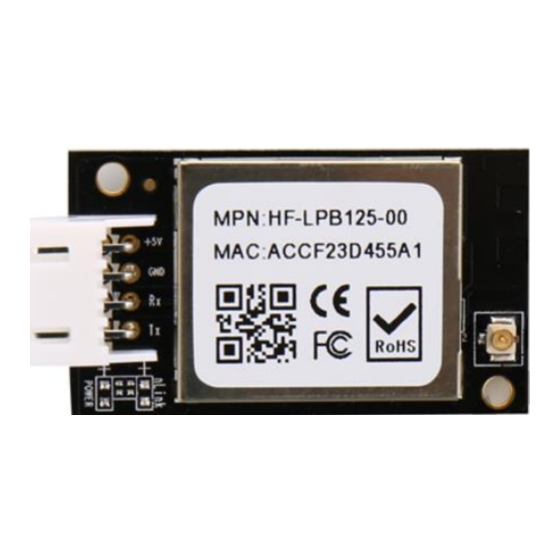
HF-LPB125 Low Power Wi-Fi Module User Manual 1.2. Hardware Introduction 1.2.1. Pins Definition Figure 1. HF-LPB125 Pins Map Table2. HF-LPB125 Pins Definition Describtion Net Name Signal Type Comments +5V Power DVDD Power 5V@250mA Ground Power UART0 UART0_RX I,PU 5V UART0 Communication... -
Page 10: Electrical Characteristics
After module is powered up, long press this button ( “Low” >= 4s ) to make the module recover to factory setting. High-Flying strongly suggest customer fan out this pin to connector or button for “Manufacture” and “ Smart Link” application. -
Page 11: Mechanical Size
Continuous Tx Supply current, STA No data transfer Supply current, STA Continuous data transfer Supply current, 1.2.3. Mechanical Size HF-LPB125 modules physical size (Unit: mm) as follows: Figure 2. HF-LPB125 Mechanical Dimension - 11 - Shanghai High-Flying Electronics Technology Co., Ltd(www.hi-flying.com) -
Page 12: External Antenna
HF-LPB125 module supports internal antenna and external antenna(I-PEX) option for user dedicated application. If user select external antenna, HF-LPB125 modules must be connected to the 2.4G antenna according to IEEE 802.11b/g/n standards. We can provide external antenna if needed. Contact with our salesman. -
Page 13: Typical Application
HF-LPB125 Low Power Wi-Fi Module User Manual 1.3. Typical Application 1.3.1. Hardware Typical Application Figure 5. HF-LPB125 Hardware Typical Application Notes: nReset- Module hardware reset signal. Input. Logics “0” effective. There is pull-up resister internal and no external pull-up required. When module power up or some issue happened, MCU need assert nRST signal “0”... -
Page 14: Functional Description
HF-LPB125 module can be configured as both wireless STA and AP base on network type. Logically there are two interfaces in HF-LPB125. One is for STA, and another is for AP. When HF-LPB125 works as AP, other STA equipments are able to connect to HF-LPB125 module directly. Wireless Networking with HF-LPB125 is very flexible. -
Page 15: Work Mode : Transparent Transmission Mode
HF-LPB125 Low Power Wi-Fi Module User Manual 2.2. Work Mode : Transparent Transmission Mode HF-LPB125 module support serial interface transparent transmission mode. The benefit of this mode is achieves a plug and play serial data port, and reduces user complexity furthest. In this mode, user should only configure the necessary parameters. -
Page 16: Firmware Update
2.7. Multi-TCP Link Connection (Reserved) When HF-LPB125 module SOCK A configured as TCP Server, it supports Multi-TCP link connection, and maximum 5 TCP clients permitted to connect to HF-LPB125 module. User can realize multi-TCP link connection at each work mode. -
Page 17: Figure 9. Multi-Tcp Link Data Transmition Structure
HF-LPB125 Low Power Wi-Fi Module User Manual Multi-TCP link connection will work as following structure: Upstream: All dates from different TCP connection or client will be transmitted to the serial port as a sequence. Downstream: All data from serial port (user) will be replicate and broadcast to every TCP connection or client. -
Page 18: Operation Guideline
HF-LPB125 Low Power Wi-Fi Module User Manual 3. OPERATION GUIDELINE 3.1. Configuration When first use HF-LPB125 modules, user may need some configuration. User can connect to HF- LPB125 module’s wireless interface with following default setting information and configure the module through laptop. -
Page 19: System Page
(MID), software version, wireless work mode and related Wi-Fi parameters. Figure 11. System Web Page 3.1.3. Work Mode Page HF-LPB125 module can works at AP mode to simplify user’s configuration, can also works at STA to connect remote server through AP router. Figure 12. Work Mode Page - 19 - Shanghai High-Flying Electronics Technology Co., Ltd(www.hi-flying.com) -
Page 20: Sta Setting Page
HF-LPB125 Low Power Wi-Fi Module User Manual 3.1.4. STA Setting Page User can push “Scan” button to auto search Wi-Fi AP router nearby, and can connect with associate AP through some settings. Please note the encryption information input here must be fully same with Wi-Fi AP router’s configration, and then it can link with AP correctly. -
Page 21: Ap Setting Page
Figure 15. AP Setting Page 3.1.6. Other Setting Page HF-LPB125 usually works at data transparent transmission mode. At this mode, the user device which connected with HF-LPB125 will connect and communicate with remote PC or server. At this page, user need setting serial port communication parameters and defines TCP related protocal parameters. -
Page 22: Account Management Page
HF-LPB125 Low Power Wi-Fi Module User Manual 3.1.7. Account Management Page This page set web server’s user name and password. Figure 17. Account Page 3.1.8. Upgrade Software Page User can upgrade new software (firmware) version through Wi-Fi. After upgrade success, need reboot it manually before new firmware valid. -
Page 23: Restore Page
HF-LPB125 Low Power Wi-Fi Module User Manual Figure 19. Restart Page 3.1.10. Restore Page After module restore factory default setting, all user configuration profile will lose. to set again, and user name and password is “admin”. HF- User can access http://10.10.100.254... -
Page 24: Usage Introduction
Ethernet Debugging Software: TCPUDPDbg 3.2.2. Network Connection User can select two methods to connect HF-LPB125 module base on dedicated application. Use HF-LPB125 STA interface. HF-LPB125 and debug PC2 connect to a wireless AP, another PC1 (or user device) connect to HF-LPB125 module with serial port: Figure 22. -
Page 25: Module Debug
Figure 24. “CommTools” Serial Debug Tools PC2 open “TCPUDPDbg” program, and create a new connection. If HF-LPB125 configured as Server mode, “TCPUDPDbg” Tools shall create “Client “mode connection. Or otherwise, create a “Server” mode connection. -
Page 26: Typical Application Examples
3.3.1. Wireless Control Application Figure 28. Wireless Control Application For this wireless control application, HF-LPB125 works as AP mode. Module’s serial port connects to user device. So, control agent (Smart phone for this example) can manage and control the user device through the wireless connection with HF-LPB125 module. -
Page 27: Transparent Serial Port Application
3.3.3. Transparent Serial Port Application For this transparent serial port application, two HF-LPB125 modules connect as below figures to build up a transparent serial port connection. One HF-LPB125 works as AP mode, another HF-LPB125 works as STA mode. Make the STA device connects to AP. -
Page 28: At+Instruction Introduction
HF-LPB125 Low Power Wi-Fi Module User Manual 4. AT+INSTRUCTION INTRODUCTION 4.1. Configuration Mode When HF-LPB125 power up, it will default works as transparent transmission mode, then user can switch to configuration mode by serial port command. HF-LPB125 UART default parameters setting as below figure, Figure 31. -
Page 29: At+Instruction Set Overview
HF-LPB125 Low Power Wi-Fi Module User Manual 2. Any other input or wrong step to UART port will cause the module still works as original mode (transparent transmission). 3. “+++” and “a” should be input in a certain period of time to make the module switch to configuration mode. -
Page 30: At+Instruction Set
HF-LPB125 Low Power Wi-Fi Module User Manual AT+<CMD>[op][para-1,para-2,para-3,para-4…]<CR> AT+: Prefix of command message; CMD: Command string; [op]: Symbol of command operator, “=” : The command requires parameters input; “NULL”: Query the current command parameters setting;... - Page 31 HF-LPB125 Low Power Wi-Fi Module User Manual Instruction Description Query module software version information BVER Query module bootloader version RELD Restore to factory default setting FCLR Erase factory setting Re-start module Help Configure Parameters Instruction Set CFGTF Copy User Parameters to Factory Default Parameters...
-
Page 32: At+E
off: Close echo When HF-LPB125 module firstly switch from transparent transmission to configuration mode, show back status is open, input “AT+E” to close show back function, input“AT+E” again to open show back function, use AT+E=on/off command to save the echo status.. -
Page 33: At+Ver
HF-LPB125 Low Power Wi-Fi Module User Manual HF-LPB125; Notes: User can set this parameter through AT+WRMID. 4.2.2.5. AT+VER Function: Query module software version information; Format: Query Operation AT+VER<CR> +ok=<ver><CR><LF><CR><LF> Parameters: ver: Module software version information;... -
Page 34: At+Cfgtf
HF-LPB125 Low Power Wi-Fi Module User Manual Format: Query Operation AT+H<CR> +ok=<command help><CR><LF><CR><LF> Parameters: command help: command introduction; 4.2.2.11. AT+CFGTF Function: Copy User Parameters to Factory Default Parameters; Format: Query Operation AT+CFGTF<CR> +ok=<status><CR><LF><CR><LF>... -
Page 35: At+Netp
HF-LPB125 Low Power Wi-Fi Module User Manual 4.2.2.13. AT+NETP Function: Set/Query network protocol parameters, Setting is valid after reset. Format: Query Operation AT+NETP<CR> +ok=<protocol,CS,port,IP><CR><LF><CR><LF> Set Operation AT+NETP=<protocol,CS,port,IP><CR> +ok<CR><LF><CR><LF> Parameters: protocol: CS: Network mode: ... -
Page 36: At+Tcpto
HF-LPB125 Low Power Wi-Fi Module User Manual sta.: if module already setup TCP link; on: TCP link setup; off: TCP link not setup; 4.2.2.16. AT+TCPTO Function: Set/Query TCP timeout; Setting is valid after reset. Format: ... -
Page 37: At+Tcpdisb
HF-LPB125 Low Power Wi-Fi Module User Manual Query Operation AT+SOCKB<CR> +ok=<protocol,port,IP><CR><LF><CR><LF> Set Operation AT+SOCKB=<protocol,port,IP><CR> +ok<CR><LF><CR><LF> Parameters: Protocol: Protocol type: TCP: Only for TCP Client UDP: UDP Client UDPS: UDP Server Port: Protocol Port in decimal, less than 65535 ... -
Page 38: At+Tcplkb
HF-LPB125 Low Power Wi-Fi Module User Manual Time: TCP timeout <= 600:600s >=0:0 means no timeout Default:300s If the SOCKB TCP don't receive any data from TCP server for TCP tmeout setting, the module will break and reconnect the TCP server. If it receive data from server, the timeout counter will be clear. -
Page 39: At+Wann
HF-LPB125 Low Power Wi-Fi Module User Manual WPA2PSK encry:Encryption algorithm NONE: When “auth=OPEN”, effective WEP-H: When “auth=OPEN” or “SHARED”, effective, in HEX format WEP-A: When “auth=OPEN” or “SHARED”, effective, in ASCII format TKIP: When ”auth= WPAPSK” or “WPA2PSK”, effective ... -
Page 40: At+Wslk
HF-LPB125 Low Power Wi-Fi Module User Manual 4.2.2.26. AT+WSLK Function: Query STA WiFi link status Format: Query Operation AT+WSLK<CR> +ok=<ret><CR><LF><CR><LF> Parameters: ”Disconnected”, if no WiFi connection; ”AP’ SSID(AP’s MAC” ), if WiFi connection available;... -
Page 41: At+Wap
HF-LPB125 Low Power Wi-Fi Module User Manual 4.2.2.30. AT+WAP Function: Set/Query AP Wi-Fi parameters. Setting is valid after reset. Format: Query Operation AT+WAP<CR> +ok=<wifi_mode,ssid,channel><CR><LF><CR><LF> Set Operation AT+WAP =<wifi_mode,ssid,channel><CR> +ok<CR><LF><CR><LF> Parameters: wifi_mode: Wi-Fi mode, include: ... -
Page 42: At+Walk
HF-LPB125 Low Power Wi-Fi Module User Manual AT+WADHCP=<status>[,ip1,ip2]<CR> +ok<CR><LF><CR><LF> Parameters: status:AP’s DHCP server function status: on:DHCP Server Open; off:DHCP Server Close: ip1: DHCP allocate IP start value. ip2: DHCP allocate IP end value. 4.2.2.33. AT+WALK ... -
Page 43: At+Ota
HF-LPB125 Low Power Wi-Fi Module User Manual num: max STA number supported for AP. 1~4: Support max 1~4 STA devices connects to module AP. 0 is default value for max 1 STA device supported. 4.2.2.36. AT+OTA Function:Set OTA Upgrade ... -
Page 44: At+Plang
HF-LPB125 Low Power Wi-Fi Module User Manual Auto: Auto power save mode(default), enter power saving mode after receive or send data in time seconds. time: Only valid in auto mode, >=2 integer value, default is 3 seconds. when value is 0, the default waiting time is still 3 seconds. -
Page 45: At+Smtlk
HF-LPB125 Low Power Wi-Fi Module User Manual +ok=<aswd> <CR><LF><CR><LF> Set Operation AT+ASWD=<aswd> <CR><LF><CR><LF> Parameters: aswd: WiFi Configuration Password (within 20 characters). 4.2.2.43. AT+SMTLK Function: Start SmartLink function Format: Query Operation AT+SMTLK<CR> SmartLink is a One-Key config function. Config the module connecting to router easily. After start SmartLink function , the module work in SmartLink status and nLink LED is fast flashing waiting for APP to push information. - Page 46 HF-LPB125 Low Power Wi-Fi Module User Manual uart_level: UART debug information output channel 0: UART0 1: UART1 - 46 - Shanghai High-Flying Electronics Technology Co., Ltd(www.hi-flying.com)
-
Page 47: Package Information
HF-LPB125 Low Power Wi-Fi Module User Manual 5. PACKAGE INFORMATION 5.1. Recommended Reflow Profile Figure 34. Reflow Soldering Profile Table9. Reflow Soldering Parameter Item Temperature (Degree) Time(Sec) Reflow Time Time of above 220 35~55 sec Peak-Temp 260 max Note: 1. Recommend to supply N2 for reflow oven. -
Page 48: Shipping Information(Tbd)
HF-LPB125 Low Power Wi-Fi Module User Manual 5.3. Shipping Information TAPE Size: 370*270*15 mm Size: 370*270*60 mm (inside) Figure 35. Shipping Information Note: 1 tape = 60 pcs 1 box = 3~4 tapes = 3~4 * 60 pcs = 180~240pcs - 48 - Shanghai High-Flying Electronics Technology Co., Ltd(www.hi-flying.com) -
Page 49: Appendix A: Http Protocol Transfer
HF-LPB125 Low Power Wi-Fi Module User Manual APPENDIX A: HTTP PROTOCOL TRANSFER HF-LPT120 module support http data transfer in throughput mode. If any detailed HTTP protocol, contact us and we may support customization. A.1. Sending HTTP Raw Data in Throughput Mode Step 1、... -
Page 50: Appendix B:references
HF-LPB125 Low Power Wi-Fi Module User Manual APPENDIX B:REFERENCES B.1.High-Flying Mass Production Tool Download Address:http://www.hi-flying.com/download_detail_dc/downloadsId=9.html B.2.SmartLink APP V7 Config Tool IOS Platform : http://www.hi-flying.com/download_detail_dc/downloadsId=42.html Android Platform: http://www.hi-flying.com/download_detail_dc/downloadsId=83.html B.3.EVK Quick Start Guide Download Address:http://www.hi- flying.com/downloadsfront.do?method=picker&flag=all&id=a974580c-9a9b-4329-a554- 6bd54aa8500d&fileId=99 B.4.Module Upgrade Download Address:http://www.hi-flying.com/download_detail_fir/downloadsId=75.html B.5.Other Tools Download Address:http://www.hi-... -
Page 51: Appendix C: Contact Information
<END OF DOCUMENT> © Copyright High-Flying, May, 2011 The information disclosed herein is proprietary to High-Flying and is not to be used by or disclosed to unauthorized persons without the written consent of High-Flying. The recipient of this document shall respect the security status of the information.
Need help?
Do you have a question about the HF-LPB125 and is the answer not in the manual?
Questions and answers