Table of Contents
Advertisement
Advertisement
Table of Contents

Related Manuals for Sibelmed SIBELSOUND 400


Summary of Contents for Sibelmed SIBELSOUND 400
- Page 1 SIBELSOUND 400 AUDIOMETRY USER MANUAL 520-700-MU2 • REV. 2.06 • 2019-03...
- Page 2 SIBEL S.A.U., Rosellón 500 bajos, 08026 BARCELONA (Spain) National Sales: Tel. 93 436 00 08 e-mail: comercial@sibelmed.com International Sales:Tel. +34 93 436 00 07 e-mail: export@sibelmed.com Technical service: Tel. +34 93 433 54 50 e-mail: sat@sibelmed.com Fax: +34 93 436 16 11 , Web: www.sibelmed.com...
-
Page 3: Table Of Contents
1. INSTRUCTIONS FOR INSTALLATION AND USE .... 10 1.1 INTRODUCTION ............11 1.2. INTRODUCTORY INFORMATION ........12 1.3. SIBELSOUND 400 AUDIOMETER MODELS ....... 13 1.4. LAYOUT OF CONTROLS, INDICATORS AND CONNECTORS . 17 2XF 1.6A H 250V ............... 19 1.5. INSTALLATION AND START-UP ........21 1.6. - Page 4 Instruction manual 3.3. INTERCOM (Optional) ..........153 3.4. FREE FIELD (Optional) ..........153 4. AUDIOMETRY TECHNIQUE ........155 5. UPKEEP, PREVENTIVE AND CORRECTIVE MAINTENANCE ............157 5.1. UPKEEP ..............158 5.2. PREVENTIVE MAINTENANCE ........159 5.3. CORRECTIVE MAINTENANCE ........160 6.
- Page 5 Instruction manual The SIBELSOUND 400 Audiometer has been designed and manufactured in accordance with the SIBEL S.A.U. In accordance with the latter directive. PRODUCT CONFORMS WITH 93/42/EEC Medical Devices Directive Class II a Revised Approved Date: 2019-03 Date: 2019-03 Antoni Picó...
-
Page 6: Safety
Instruction manual Instruction manual SAFETY SPECIAL PRECAUTIONS The SIBELSOUND 400 audiometer has been designed to the highest safety standards. You should read all operating instructions carefully before operating the device. Failure to do so could cause injury to the user or patient and damage to the equipment and/or accessories. - Page 7 Instruction manual Profile of the patient: Age:> 4 years until old age Weight: without limitations Height: without limitations Health status: physical and mental condition necessary to understand the doctor's instructions and to be able to indicate the acoustic perceptions. THE ROLE OF THE PATIENT IN THE USE OF THE AUDIOMETER The audiometry tests require the cooperation of the patient.
- Page 8 Instruction manual Instruction manual ELECTRICAL RISKS DO NOT tamper with the integrity of the system's electric earth connection. Protection against electrical discharge is provided by the connection of the chassis to an electrical earth connection. The earth connection is only effective when the three-wire power cable supplied with the equipment is connected to a suitably earthed electrical socket.
- Page 9 For this reason, products which can cause interference (radios, mobile telephones, etc.) must be kept away from the audiometer. SibelSound 400 as an electronic device, and special precautions regarding Electromagnetic Compatibility must be taken. The device must be installed following the electromagnetic guide in Annex 1.
-
Page 10: Instructions For Installation And Use
Instruction manual Instruction manual INSTRUCTIONS FOR INSTALLATION AND USE 520-700-MU2 • REV. 2.06... -
Page 11: Introduction
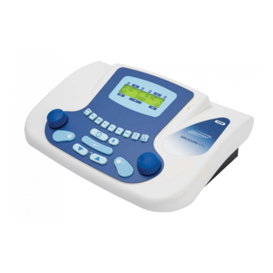
Instruction manual 1.1 INTRODUCTION The SIBELSOUND 400 clinical audiometer is a compact two-channel device, the main components of which are a tone generator, a noise generator, a set of headphones for air conduction, a vibrator for bone conduction and an alphanumeric liquid crystal screen. -
Page 12: Introductory Information
Instruction manual 1.2. INTRODUCTORY INFORMATION This instruction manual applies to all models and all options which may be included in the SIBELSOUND 400 audiometer. Accordingly, only those functions or options which are found in your particular model will be relevant. -
Page 13: Sibelsound 400 Audiometer Models
Instruction manual 1.3. SIBELSOUND 400 AUDIOMETER MODELS The SIBELSOUND 400 audiometer comprises six different models: SIBELSOUND 400 A SIBELSOUND 400 AM SIBELSOUND 400 AO SIBELSOUND 400 AOM SIBELSOUND 400 AOM+ SIBELSOUND 400 SUPRA The table below shows each model's built-in features as standard (Shadedo) and other items which can be included as optional (White). - Page 14 ARICULARES VIA AEREA / EARPHONE SET 03078 SUPRESOR DE RUIDO VA / AUDIOCUPS AC __________ MANUAL DE USO DEL SIBELSOUND 400 (Doc. 520-700-MU1) / SIBELSOUND 400 USER MANUAL (Doc. 520-700-MU2) __________ GUIA RAPIDA DE USO SIBELSOUND 400 (Doc. 520-711-GR1) / SIBELSOUND 400 QUICK REFERENCE (Doc. 520-711-GR2) SOFTWARE AUDIOMETRÍA W-50 DEMO/ AUDIOMETRY DEMO...
- Page 15 Instruction manual RELACIÓN DE CONTENIDO / PACKING LIST Página 2 de 2 SIBELSOUND 400 520-708-010 REV. 5 07/11 CÓDIGO DESCRIPCIÓN CANT. CODE QTY. DESCRIPTION 06408 OPCION FIRMWARE FRECUENCIAS INTERMEDIAS INTERMEDIATED FREQUENCY SOFTWARE OPTION 06402 OPCION FIRMWARE FRECUENCIAS MUSICALES MUSICAL FREQUENCIES FIRMWARE OPTION...
- Page 16 In addition to the necessary routine maintenance of the SIBELSOUND 400 audiometer, we recommend calibrating the transducers and performing a general check of the safety systems, adjustments, functions, etc. at least once every twelve months (ISO 8253-1).
-
Page 17: Layout Of Controls, Indicators And Connectors
Instruction manual 1.4. LAYOUT OF CONTROLS, INDICATORS AND CONNECTORS FRONT PANEL 520-700-MU2 • REV. 2.06... - Page 18 Instruction manual Instruction manual Display. Doctor's microphone. Attenuators: to increase or decrease the signal level applied to the patient (dBs) and select the menu options. Reset: deletes certain information. Sisi: generates the manual increments for the SISI test. Print: prints the audiometric file which has been created, if thresholds have previously been saved.
-
Page 19: 2Xf 1.6A H 250V
Instruction manual REAR PANEL 520-700-MU2 • REV. 2.06... - Page 20 Instruction manual Instruction manual Bone Conduction Air Conduction High Frequency Air Conduction Patient Microphone Doctor's Microphone Patient response button Free field Auxiliary input Intercom headset Parallel printer RS·232·C connection USB – PC connection USB connection – Printer Terminal for mains earth connection POWER input 100V - 240V Fuse holder NOTE: The 2 fuses used are 1.6A, fast (F), and high...
-
Page 21: Installation And Start-Up
EN – 60601-1), the SIBELSOUND 400 audiometer is categorised as CLASS I equipment. To power up, the SIBELSOUND 400 audiometer needs a 100V - 240V - 50 /60Hz mains connection with corresponding earth terminal in accordance with current UNE (IEC) standards. - Page 22 Instruction manual Instruction manual The sequence of operations to prepare the SIBELSOUND 400 to carry out audiometric tests is as follows: Main power switch in position “0” OFF. Connect the mains power cable to the device and to a 100V - 240V - 50 / 60Hz mains connection.
- Page 23 Instruction manual START-UP To start up the SIBELSOUND 400 audiometer, move the main power switch to position “I” ON. The following screen will appear for several seconds: SIBELMED SIBELSOUND 400 The equipment then performs a self-check in which it tests whether all the accessories are connected and whether the original calibration is correct.
- Page 24 Instruction manual Instruction manual Both the keyboard and screen are located on the front panel of the device. The screen consists of two lines of 16 alphanumeric characters each. Printer All models can be connected, whether as a standard feature or an option, to an external printer, if this option has been selected previously in the Configuration.
-
Page 25: Function Tree
1.6. FUNCTION TREE For a better understanding of the structure of the SIBELSOUND 400 audiometer we have included its function tree. In general, it is possible to navigate through the various menu options by means of the keys... - Page 26 Instruction manual Instruction manual 1. TESTS 1. PURE TONE 2. SISI 3. SPEECH 4. FOWLER 5. TONE DECAY 6. LÜSCHER 7. WEBER 8. PURE TONE HF 9. FREE 2. CONFIGURATION 1. SAVE CONFIGURATION 2. MODIFY DEFAULT 3. RESET DEFAULT 4. DIAGNOSIS 5.
-
Page 27: Personalising The Device
To prevent against this anomaly, the SIBELSOUND 400 audiometer has a configuration program which allows a user to define their initial work configuration and reload it every time they turn the device on. - Page 28 Instruction manual Instruction manual PERSONALISING DIAGNOSIS Take the following steps to select the type of diagnosis that will appear in the report: From the Main Menu access the option MENU 2. CONFIGURATION Select CONFIGURATION 4. DIAGNOSIS Choose the diagnosis you require from the following: 1.
- Page 29 Instruction manual PERSONALISING FREQUENCIES To select the frequencies for inspection in the Pure Tone and Free tests: From the Main Menu access the option MENU 2. CONFIGURATION CONFIGURATION 5. FREQUENCY FREQUENCY 1. FREQ. SEL. Select CONFIGURATION 5. SEL. FREQ Choose the desired frequencies. CUSTOMISING MUSICAL FREQUENCIES To select the musical frequencies in the Pure Tone and Free tests:...
- Page 30 Instruction manual Instruction manual Select CONFIGURATION 5. FREQUENCY FREQUENCY 1. MUSICAL FREQ. Use the attenuators to choose whether or not you want to use musical frequencies and press “ENTER”. FREQUENCY Mus. Freq. ON(*) The musical frequencies appear on the chart below and correspond to traditional frequencies when shown on the screen or on reports: MUSICAL...
- Page 31 Instruction manual option selected: C A HZ 1000* PERSONALISING PRINTING To select the printer: From the Main Menu access the option MENU 2. CONFIGURATION Select CONFIGURATION 6. PRINTER Choose the printer you wish to use PERSONALISING LANGUAGE To personalise language: From the Main Menu access the option MENU 2.
- Page 32 Instruction manual Instruction manual PERSONALISING CALIBRATION To select the correction table (ISO389 or ANSI S3.6): From the Main Menu access the option MENU 3. MAINTENANCE Select MAINTENANCE 2. CALIBRATION CALIBRATION 1. ANSI / ISO The following screen appears ANSI / ISO F1: YES F3: NO Press...
- Page 33 Instruction manual Select MAINTENANCE 2. CALIBRATION CALIBRATION 2. CAL. WARNING The following screen appears Last Calibration 01-05-08 With the date of the last calibration. Press The following screen appears Maint. Interval Days: 365 Enter the number of days until the next calibration is to take place.
- Page 34 Instruction manual Instruction manual RECOVERING THE DEFAULT CALIBRATION To recover the default calibration: From the Main Menu access the option MENU 3. MAINTENANCE Select MAINTENANCE 2. CALIBRATION CALIBRATION 3. DEFAULT CAL The following screen appears DEFAULT CAL F1: YES F3: NO Press to recover the default calibration.
- Page 35 Instruction manual PERSONALISING CONTRAST To personalise screen contrast: From the Main Menu access the option MENU 2. CONFIGURATION Select CONFIGURATION 8. CONTRAST Choose the required contrast. PERSONALISATION OF DATE AND TIME To configure the device date and time: From the Main Menu access the option MENU 2.
- Page 36 Instruction manual Instruction manual AUTOMATIC MASKING To select automatic masking: From the Main Menu access the option MENU 6. AUTO MASK Use the attenuators to select whether or not to use automatic masking and press AUTO MASK Auto Mark ON (*) Before performing a masked test, adjust the intensity difference between the mask channel and the signal channel by moving the masking channel attenuators.
- Page 37 Instruction manual MENU 7. AUTO SAVE Use the attenuators to choose whether or not you want to saved automatically the thresholds and press AUTO SAVE Auto Save. ON (*) When performing a Pure Tone test, after the entry of a patient reference and the appliance of signal;...
- Page 38 Instruction manual Instruction manual MENU 9. FREEE Press simultaneously keys. Use the attenuators to choose whether or not you want to enable the High Frequency option and press HIGH FREQ High Freq ON (*) INITIAL CONFIGURATION The process to specify the initial working configuration is as follows: Set the controls to the positions which you would like them to be in when the audiometer is turned on.
- Page 39 Instruction manual MENU 2. CONFIGURATION and press the Using the keys select the option: CONFIGURATION 1. SAVE CONF. and press the key. The following message appears: SAVE CONF. F1: YES F3: NO Press to confirm SAVE CONF. CONF. SAVED Once this has been done, the audiometer will set itself in the selected position each time it is turned on.
- Page 40 Instruction manual Instruction manual DEFAULT CONFIGURATION To modify the default configuration: From the Main Menu access the option MENU 2. CONFIGURATION Select CONFIGURATION 2. MODIF DEFAULT The following message appears: MODIF. DEFAULT F1: YES F3: NO Press to confirm MODIF. DEFAULT DEFAULT CHANGED To copy the default configuration to the user's configuration: From the Main Menu access the option...
-
Page 41: Audiometric Tests
RESET DEFAULT DEFAULT RESET 1.8. AUDIOMETRIC TESTS The SIBELSOUND 400 audiometer supports many types of audiometric investigations. For ease of use, the Main Menu allows you to access the various tests and, if you wish, prepare the printed report automatically. - Page 42 Free-field audiometry is carried out in a similar way to tone audiometry via air conduction. This test can be carried out using air conduction with any SIBELSOUND 400 model. Free-field tests, via bone conduction and masking are only integrated in some models and are optional in others.
- Page 43 Speech audiometry has many variants not addressed in this manual, which are left to specialist criteria. It can be carried out with the SIBELSOUND 400 AOM+, SUPRA and SUPRA models, and other models if incorporated as an option.
- Page 44 5 dB steps until it can again be heard and again successively until the patient confirms he can hear the sound for one minute. It is performed with the SIBELSOUND 400 SUPRA model and also with the other models if this option is included. LUSCHER The Luscher test consists in distinguishing between signal modulation variations.
- Page 45 20.000 Hz and is applied by the air HF conduction. It also allows to realize masking with narrow band noise and white noise sources. It’s an option in the SIBELSOUND 400 AOM, AOM+ and SUPRA models. FREE AUDIOMETRY This audiometer option MUST NOT BE CONFUSED WITH FREE FIELD.
-
Page 46: Procedure For Tone Audiometry
• Is masking required or not? • When does the patient's response match the signal? (The SIBELSOUND 400 gives warning of inconsistencies) • Is there some external noise or patient response which could invalidate the test? •... - Page 47 Instruction manual Therefore, high noise levels should be avoided before the test or this should be indicated on the report. To avoid errors due to physical effort, we recommend that the patient be at the location of the test at least five minutes before it takes place. An otoscopic examination is usually carried out by a qualified person, to establish whether there is an obstruction in the external ear canal that needs to be removed.
- Page 48 Instruction manual Instruction manual WARNING: THE TRANSDUCER CALIBRATION IS STORED IN THE EQUIPMENT, IF YOU USE A TRANSDUCER NOT CALIBRATED, AUDIOMETRIC TESTS WILL NOT BE VALID. PREPARING THE AUDIOMETER Before explaining the procedure for performing the test, it is convenient to present the characters which may appear on the screen.
- Page 49 Instruction manual Select with + left or right attenuator according to channel. On the second line: ABC and NOP Signal level applied to the patient in "dB" ABC right channel. Select with right attenuator. NOP left channel. Select with left attenuator. DE and LM Two cursors that indicate that a signal is being applied to the patient.
- Page 50 Instruction manual Instruction manual these are the following: HZ C A 1000 Push the NEW PATIENT Ref: Enter the reference and press If the thresholds of the previous patient have not been saved to the database, the unit displays a screen for saving them: SAVE PREVIOUS F1: YES F3: NO...
- Page 51 Instruction manual NOTE: When ELI diagnosis is selected, after the previous screen the following appear: NEW PATIENT Age: NEW PATIENT Sex: Press A HZ C A HZ C Using the corresponding attenuator, select the route of application of the signal for each channel: air (A), bone (O), free field (F) or disabled (-).
- Page 52 Instruction manual Instruction manual Using the corresponding attenuator, select the mode of presentation of the signal for each channel: continuous signal (C) or pulsating signal (P). Choose the intensity of the signal by rotating the attenuators until the required value is found. A HZ C A HZ C 1000 Select the frequency of the signal (press...
- Page 53 Instruction manual These keys have two positions: "direct and inverted". The "direct" position applies the signal to the patient when the key is pressed, otherwise no signal is applied. The "inverted" position blocks the signal to the patient when the key is pressed, otherwise a signal is applied. You can switch from one option to the other by holding down key for the relevant channel and pressing...
- Page 54 A description of each type of tone audiometry in accordance with standard ISO 8253-1, is shown below DETERMINATION OF THE HEARING THRESHOLD VIA AIR CONDUCTION WITHOUT MASKING The SIBELSOUND 400 audiometer provides the following frequencies and pure tone levels for application by air conduction: 1000...
- Page 55 Instruction manual When the patient presses the response button, the response is displayed on the screen as follows: l l l l l l l l l l l l 1000 If the patient presses the button in the absence of a signal, the message "NO SIGNAL"...
- Page 56 Instruction manual Instruction manual Following the response, reduce the level in 10 dB steps until there ceases to be a response and then start to increase it again (new "ascent"). Continue the process until there have been three responses at the same level within a maximum of five ascents (auditory responses within three ascents, abbreviated method).
- Page 57 To avoid the test tone being heard by the ear other than the one being tested, it is necessary to apply a masking noise to that ear. The SIBELSOUND 400 audiometer provides Narrow Band Noise NBN with the following levels of masking in each of the frequencies for application via air conduction:...
- Page 58 Make a note of the correct level of masking. DETERMINATION OF THE HEARING THRESHOLD VIA BONE CONDUCTION WITHOUT MASKING The SIBELSOUND 400 audiometer provides the following frequencies and pure tone levels for application by bone conduction: 1000...
- Page 59 CONDUCTION WITHOUT MASKING. DETERMINATION OF THE HEARING THRESHOLD VIA BONE CONDUCTION WITH MASKING The SIBELSOUND 400 audiometer provides Narrow Band Noise NBN masking with the following levels of masking in each of the frequencies for application via bone conduction: 1000...
- Page 60 Instruction manual Instruction manual thresholds via bone conduction with masking is described below. Apply a test tone to the ear being investigated at a level equal to the hearing threshold via bone conduction without masking. Select narrow band noise NBN with the other audiometer channel and apply a level of effective masking to the other ear equal to the threshold hearing level via air conduction for the latter.
- Page 61 Instruction manual the hearing threshold for those frequencies where the subject failed the screening test. In this case, the procedure for determining thresholds is as described in the section DETERMINATION OF THE HEARING THRESHOLD VIA AIR CONDUCTION WITHOUT MASKING . The general aspects and the preparation for and instructions to the patient are as described at the beginning of that section.
-
Page 62: Procedure For Sisi Test
Instruction manual Instruction manual the test at this frequency. If the third tone or the first two tones were not heard by the subject, they have not passed the screening test at this frequency. Select another frequency and repeat point Once the right ear has been tested, repeat the process described in points , blocking the right channel signal... - Page 63 Instruction manual In this test the signal source to be used is a Pure Tone in Hz. The characters which can appear in each of the positions on the screen when a test is being carried out are described below. On the first line: A Route of application (A Air Conduction / - Disabled) Select with...
- Page 64 Instruction manual Instruction manual Select with On pressing the key : EFG Intensity of the increases in signal (From 0,2 to 5 dB). Select with right attenuator. N O P S p a c i n g b e t w e e n a p p l i c a t i o n s o f t h e s i g n a l (MAN: Manual / 1- 9 seconds: automatic).
- Page 65 Instruction manual Using the keys select the option: MENU 1. TEST TEST 2. SISI and access the test by pressing the key, (the test can also be accessed from any other test by pressing the corresponding key). A screen appears showing the configured options. By default these are the following: A R00 S A S00 - 1000...
- Page 66 Instruction manual Instruction manual Likewise, a test being performed can be restarted by entering the same reference again: NEW TEST F1:YES F3:NO Select F1 to delete all the thresholds saved for the current test and start the test again. NOTE: When ELI diagnosis is selected, after the previous screen the following appear: NEW PATIENT Age:...
- Page 67 Instruction manual Using the corresponding attenuator select the signal presentation mode for each channel: SISI (S) o DISABLE (-). Select the frequency of tone to apply from 500, 1000, 2000 or 4000 Hz (Press until the required value is found). A R00 S A S00 - 1000 Press the...
-
Page 68: Procedure For Speech Audiometry Test
Instruction manual Instruction manual • Normal: press the key for the channel corresponding to the ear being tested and keep it pressed for the duration of the test. • Inverted: keep the key pressed, press the key and release them both. The signal is then applied when you are NOT pressing the key. - Page 69 Instruction manual Before explaining the procedure for performing the test, it is convenient to present the characters which may appear on the screen. These show the operational status of the device at all times. As mentioned previously, the screen consists of two lines of 16 alphanumeric characters each.
- Page 70 Instruction manual Instruction manual NQ F1: AUX / MIC DV The input device (MICROPHONE (microphone for the technician) / AUXILIARY) appears in positions 4 to 13. The selected device starts blinking. Select with On the second line: ABC and NOP Signal level applied to the patient in "dB" ABC right channel.
- Page 71 Instruction manual words pronounced) using a list of words spoken live or via recorded material. There is little standardisation of this test either in terms of the procedure to be followed or the material to use, so these are left to the discretion of the specialist. In this section we only provide a basic description of how to use the equipment in this mode.
- Page 72 Instruction manual Instruction manual NEW PATIENT Ref: Enter the reference and press If the thresholds of the previous patient have not been saved to the database, the unit displays a screen for saving them: SAVE PREVIOUS F1:YES F3:NO Likewise, a test being performed can be restarted by entering the same reference again: SAVE PREVIOUS F1:YES...
- Page 73 Instruction manual Using the corresponding attenuator, select the route of application of the signal for each channel: air (A), free field (F). Press Using the corresponding attenuator, select the signal source: speech audiometry (SP), or masking with speech noise (SPN). A SP C A SP C SPEECH SPEECH...
- Page 74 Instruction manual Instruction manual applied to the patient. Connect the microphone for the technician carrying out the test if it is a live voice test or the tape recorder if recorded material is being used. If the audiometer is installed in a sound-proof booth, connect the patient's microphone and the headset for the technician carrying out the test to the corresponding connection points.
-
Page 75: Procedure For Performing The Fowler Test
Instruction manual is neither increment nor loss in the level of signal applied to the patient (0 dB). Bear in mind that the level of signal applied to the patient depends on the dB level selected for each channel. If the indicator for the level of signal in speech audiometry is fully lit up, this represents an increase in the applied signal of 3 dB. - Page 76 Instruction manual Instruction manual ABCDEFGHIJKLMNOP ABCDEFGHIJKLMNOP On the first line: A and J Application conduction (A Air Conducted / - Disabled) Select with + left or right attenuator according to channel. CDE and LMN Signal source (HZ Frequency in Hz of Pure Tone) Select with + left or right attenuator according to channel.
- Page 77 Instruction manual The Fowler test is also referred to as the Alternate Binaural Loudness Balance test or ABLB. This test is performed to ascertain whether there is recruitment when the hearing threshold is normal or less than 30 dB and the other ear shows a hearing loss of between 25 and 60 dB.
- Page 78 Instruction manual Instruction manual A HZ 1000 Press the key: NEW PATIENT Ref: Enter the reference and press If there are thresholds that have not been saved (recorded) in the database from the previous patient, the equipment will display the following screen which allows them to be saved: SAVE PREVIOUS F1: YES F3: NO...
- Page 79 Instruction manual NEW PATIENT Sex: Male Press the Use the corresponding attenuator to select the application conduction of the signal for each channel: aerial (A), or disabled (-). Press TONE TONE Use the corresponding attenuator to select the source of the signal for each channel: in this case only the frequency in Hz of the pure tone (HZ).
- Page 80 Instruction manual Instruction manual 1000 Select the frequency of the tone between 125 and 8000 Hz by using the 1000 The test can be carried out in two different ways: • Normal: by pressing the of the corresponding channel. • Inverted: by keeping the key pressed, pressing the INVER key and releasing both of them.
-
Page 81: Tone Decay Test Procecure
Instruction manual DEL. THRESHOLDS F1:YES F3: NO 1.13. TONE DECAY TEST PROCECURE The general aspects and the preparation for and instructions to the patient are as described at the beginning of section 1.9. PROCEDURE FOR TONE AUDIOMETRY. Before explaining this test procedure, it is advisable to describe the characters which may appear on the screen. - Page 82 Instruction manual Instruction manual G and P Presentation mode of the signal (C Continuous) Select with + left or right attenuator according to channel. On the second line: ABC and NOP Signal level applied to the patient in «dB» ABC right channel. Select with right attenuator. NOP left channel.
- Page 83 Instruction manual above the hearing threshold and a frequency of 250, 500, 1000, 2000 or 4000 Hz. The test starts by applying the tone using the SIGNAL key in "direct" or "inverted" mode for 60 seconds if the response persists. Otherwise, the tone level is increased. The patient responds through the warning connection while he hears the signal.
- Page 84 Instruction manual Instruction manual 1000 Press the NEW PATIENT Ref: Enter the reference and press If there are thresholds that have not been saved (recorded) in the database from the previous patient, the equipment will display the following screen which allows them to be saved: SAVE PREVIOUS F1: YES F3: NO...
- Page 85 Instruction manual NEW PATIENT Sex: Press the Use the corresponding attenuator to select the application conduction of the signal for each channel: air (A), bone (O), free field (C - optional), disabled (-) or (F - optional). Press TONE TONE Use the corresponding attenuator to select the source of the signal for each channel: in this case only frequency in Hz of Pure Tone (HZ).
-
Page 86: Luscher Test Procedure
Instruction manual Instruction manual until the required value is found. 1000 Select the frequency of the applied tone between 250, 500 1000, 2000 and 4000 Hz using the 1000 The test can be carried out in two different ways: • Normal: by pressing the of the corresponding channel. - Page 87 Instruction manual PROCEDURE FOR TONE AUDIOMETRY. Before explaining this test procedure, it is advisable to describe the characters which may appear on the screen. These show the operational status of the device at all times. As mentioned previously, the screen consists of two lines of 16 alphanumeric characters each.
- Page 88 Instruction manual Instruction manual DE and LM Two cursors that indicate that the signal is being applied to the patient. DE right channel. Apply signal with LM left channel. Apply signal with FGHIJ Frequency in Hz of the applied tone Select with On pressing the for 1 second:...
- Page 89 Instruction manual frequency with bandwidth modulation in the ear being studied. He must press the warning connection when he ceases to hear or starts to hear the ripple in the tone, depending on whether its level is being turned up or down. With the audiometer set up as indicated in section 1.5 INSTALLATION AND START-UP, the test proceeds as follows: Press the...
- Page 90 Instruction manual Instruction manual the following screen which allows them to be saved: SAVE PREVIOUS F1: YES F3: NO Similarly, the current test can be cancelled by entering the same reference again: NEW TEST F1: YES F3: NO Select to delete all the thresholds of the current test that have been saved and start it again.
- Page 91 Instruction manual Press A HZ M TONE TONE Use the corresponding attenuator to select the source of the signal for each channel: in this case only the frequency in Hz of the pure tone (HZ). Press the HZ M MODULA. MODULA.
-
Page 92: Weber Test Procedure
Instruction manual Instruction manual HZ M Select the modulation bandwidth level from 0.2, 0.3, 0.4, 0.5, 0.6, 0.8, 1, 2, 3, 4 or 5 dB by rotating the attenuator of the corresponding channel. The frequency setting of the modulation signal is fixed at 2.5 Hz. Press ENTER to accept the changes and return to the test screen. - Page 93 Instruction manual previously, the screen consists of two lines of 16 alphanumeric characters each. On the first line, the characters located in positions 0 to 7 refer to the right channel and those located at positions 8 to 15 to the left channel. The characters which can appear in each of the positions on the screen when this test is being carried out are described below.
- Page 94 Instruction manual Instruction manual LM left channel. Apply signal with FGHIJ Frequency in Hz of the applied tone Select with The Weber test consists in applying a tone level 15 dB above the frontal bone threshold of the subject at frequencies between 250 and 4000 Hz.
- Page 95 Instruction manual Press the and select the option: MENU 1. TESTS TESTS 7. WEBER And access the test by pressing the A screen appears showing the configured options. By default these are the following: 1000 Press the NEW PATIENT Ref: Enter the reference and press If there are thresholds that have not been saved in the database from the previous patient, the equipment will display...
- Page 96 Instruction manual Instruction manual same reference again: NEW TEST F1: YES F3: NO Select to delete all the thresholds of the current test that have been saved and start it again. NOTE: When ELI diagnosis is selected, the following screen will appear afterwards: NEW PATIENT Age: NEW PATIENT...
- Page 97 Instruction manual signal for each channel: in this case only the frequency in Hz of the pure tone (HZ). Press the CONTEN. CONTEN. Use the corresponding attenuator to select the signal presentation mode for each channel: in this case only the continuous signal (C).
-
Page 98: Pure Tone Hf Test Procedure
Instruction manual Instruction manual the signal will appear when the silencers are NOT pressed. In this test, the side and the frequency at which the patient states hearing with the greatest intensity are recorded. To save the threshold the key must be pressed. The following screen will appear: R.E. - Page 99 Instruction manual The characters which can appear in each of the positions on the screen when this test is being carried out are described below. ABCDEFGHIJKLMNOP ABCDEFGHIJKLMNOP On the first line: A and J Application conduction (A Air Conducted / - Disabled) Select with + left or right attenuator according to channel.
- Page 100 The Pure Tone HF test consists of a pure tone test, in which the hearing thresholds can be determined for frequencies higher than 8.000 Hz. The SIBELSOUND 400 audiometer allows the 9.000, 10.000, 11.200, 12.500, 14.000, 16.000, 18.000 y 20.000 Hz frequencies, besides the frequencies of 125 to 8.000 Hz.
- Page 101 Instruction manual TESTS 8. PURE TONE HF And access the test by pressing the key. A screen appears showing the configured options. By default these are the following: 8000 Press the key: NEW PATIENT Ref: Enter the reference and press If there are thresholds that have not been saved in the database from the previous patient, the equipment will display the following screen, which allows them to be saved:...
- Page 102 Instruction manual Instruction manual NOTE: When ELI diagnosis is selected, the following screen will appear afterwards: NEW PATIENT Age (y): NEW PATIENT Sex: Press the Use the corresponding attenuator to select the application conduction of the signal for each channel: air (A) or disabled (-).
- Page 103 Instruction manual Use the corresponding attenuator to select the signal presentation mode for each channel: continuous (C) or pulsating (P). Choose the intensity of the signal by rotating the attenuators until the desired value is found. 8000 Select the frequency of the applied tone in the range of 125 to 20.000 Hz by using the keys.
-
Page 104: Procedure For Free Audiometry
Therefore options have been provided for the SIBELSOUND 400 audiometer to simplify the execution of each kind of test. However, specialists for whom the options described are too... - Page 105 REF. TONE ON 1dB 1.18. DIAGNOSTIC CALCULATIONS The SIBELSOUND 400 audiometer can determine the following diagnoses based on their respective parameters: “MINISTRY” DIAGNOSIS ACCORDING TO THE MINISTRY OF LABOUR AND SOCIAL AFFAIRS OSB No. 22 (January 26, 2000)
-
Page 106: Printing And Saving Audiometric Tests
Instruction manual Instruction manual 1.19. PRINTING AND SAVING AUDIOMETRIC TESTS The SIBELSOUND 400 audiometer can print and/or save certain audiometric tests to the device itself or to an external database. The audiometer can save the hearing thresholds detected to a temporary memory. As mentioned above, this operation... - Page 107 Instruction manual • LUSCHER • WEBER • PURE TONE HF. C. Printing the Report The process to follow when carrying out the tests you wish to print is as follows: Press the key and assign a reference number of up to 10 characters to the patient being tested.
- Page 108 Instruction manual Instruction manual via the following screen: SAVE THRESHOLD F1: YES F3:NO If the audiometry is pure tone, this warning appears when there is a patient registered in the device, the signal has been applied and the user attempts to change the frequency, the path or the source SISI TEST In this test, once the twenty 1 dB signal increases have...
- Page 109 Instruction manual The save threshold warning appears when there is a patient registered in the device, the signal has been applied and an attempt is made to modify the intensity, the pathway or the signal source, or if an attempt is made to reset the number of correct responses.
- Page 110 Instruction manual Instruction manual At that time, the technician must press the key and the machine will save the modulation level and the frequency. The save threshold warning appears when a patient has been registered on the machine, a signal has been applied and someone attempts to change the frequency, the signal conduction or the source.
- Page 111 Instruction manual pressing the key. The warning to record the threshold appears when a patient has been registered on the machine, signal has been applied and someone attempts to change the frequency, signal conduction or source. FREE AUDIOMETRY Having performed the tests, if you entered via this option you can neither print nor save the results in the database.
- Page 112 Instruction manual Instruction manual A --- A --- 60 100% 75% 60 4. Fowler: threshold, frequency and conduction. 1000 5. Tone Decay: seconds (on the first line) and threshold, frequency and conduction (on the second line). 1000 6. Luscher: threshold (modulation level), frequency and conduction.
- Page 113 An audiometric file output via a printer is shown at the end of this chapter. SAVING AUDIOMETRIC DATA IN THE INTERNAL DATABASE The SIBELSOUND 400 audiometer has a FLASH memory with capacity for more than 1000 tone tests via air conduction and bone conduction in both channels at the frequencies 500, 1000, 2000, 3000 and 4000 Hz.
- Page 114 Instruction manual Instruction manual This stored information can be used for: • Subsequent transfer to a database on a PC (See section 1.15. COMMUNICATIONS SYSTEMS) • Printing using an external printer. SAVING A TEST To save a test in the database press the key.
- Page 115 Instruction manual DATABASE 1. VER and press . The user can also access the previous screen directly by pressing the key for 1 second from the test screen. If there are no thresholds to save, the key can be pressed as normal. The following screen appears: Rec 1/10 12345...
- Page 116 Instruction manual Instruction manual The following screen appears: 12345 TONE 21-07-05 11 At this point you may: • Print the tests for the selected patient by pressing 12345 TONE PRINTING • Select other tests for the same patient (if any), using the attenuators.
- Page 117 Instruction manual and press The user can also access the previous screen directly by pressing the key for 1 second from the test screen. If there are no thresholds to save, the key can be pressed as normal. Then select DATABASE 2.
- Page 118 Instruction manual Instruction manual Access the Options Menu by pressing the key. Select the option MENU 4. DATABASE and press The user can also access the previous screen directly by pressing the key for 1 second from the test screen. If there are no thresholds to save, the key can be pressed as normal.
- Page 119 Instruction manual DELETE A PATIENT FROM THE DATABASE To delete a patient from the internal database proceed as follows: Access the Options Menu by pressing the . key. Select the option MENU 4. DATABASE and press . The user can also access the previous screen directly by pressing the key for 1 second from the test screen.
-
Page 120: Communications Systems
1.20. COMMUNICATIONS SYSTEMS One of the features of the SIBELSOUND 400 is the Communications System with other media which allows it to: • Transfer information from the device's internal database to a PC. - Page 121 PC. COMMUNICATION IN REAL TIME WITH THE PC The SIBELSOUND 400 audiometer can communicate in real time with a PC. This allows the data of the tests being carried out to be viewed directly on the computer screen.
-
Page 122: Updating The Unit Firmware
For information relating to the Audiometry Software W-50, see the Instruction Manual. 1.21. UPDATING THE UNIT FIRMWARE The SIBELSOUND 400 audiometer from SIBEL S.A.U. is provided with a firmware updating and maintenance process. Before updating, make sure that the audiometer is operating and connected to the PC. -
Page 123: Maintenance Program
Instruction manual WARNING: DO NOT CANCEL THIS LOADING PROCESS ONCE IT HAS BEEN STARTED. On completion, a “transmission correct” message appears. For the new firmware to work correctly, the user must exit the loading screen, switch the audiometer off and switch it back on. - Page 124 Instruction manual Instruction manual • Check the device hardware (CPU and LCD). • View the updating password and version of the equipment. • Test that the keyboard and the printer work properly. • Reset the device. The options can be adjusted from three menus: •...
- Page 125 Instruction manual Press to start the various CPU tests. When the tests are completed, the following screen appears: RESTART TEST F1:YES F3:NO Press to exit. In the event of errors, a message is displayed for each error, scroll forward using the key.
- Page 126 Instruction manual Instruction manual To exit press the key for 1 second. PRINTER TEST Select the option: TEST DEVICE 4. PRINTER This verifies that the printer is functioning correctly by printing out a test report. UPDATING PASSWORD Select the option: TEST DEVICE 5.
- Page 127 Instruction manual TEST DEVICE 7. RESET DEVICE The following screen appears: RESET DEVICE F1:YES F3:NO Press to reset the device. Warning: THIS WILL ALSO RESULT IN THE LOSS OF BOTH USER AND STANDARD CONFIGURATION, WHICH WILL BE REPLACED BY THE DEFAULT FACTORY CONFIGURATION OF THE DEVICE.
- Page 128 Instruction manual Instruction manual To adjust the level of the monitor, select the following option: MAINTANCE 3. MONITOR Place the technician headphones, apply the signal with the keys or use the attenuators to adjust the level of the monitor to the desired setting. To deactivate the monitor function, adjust the setting to 0.
- Page 129 Instruction manual Apply the signal using the keys and use the attenuators to adjust the level of the devices to the desired setting. To change the device, press the AUXILIARY This menu is used to adjust the level of the auxiliary signal that can be used in the Speech test (optional).
- Page 130 Instruction manual Instruction manual 520-700-MU2 • REV. 2.06...
- Page 131 Instruction manual 520-700-MU2 • REV. 2.06...
- Page 132 Instruction manual Instruction manual 520-700-MU2 • REV. 2.06...
- Page 133 Instruction manual 520-700-MU2 • REV. 2.06...
- Page 134 Instruction manual Instruction manual 520-700-MU2 • REV. 2.06...
-
Page 135: Technical Specifications
Instruction manual . TECHNICAL SPECIFICATIONS 520-700-MU2 • REV. 2.06... -
Page 136: Types Of Tests
As described in chapter 1 of the INSTRUCTIONS FOR INSTALLATION AND USE, there are six different models of the SIBELSOUND 400 and they can each be enhanced with options not installed as standard. Therefore, the technical specifications set out below correspond to a device which has all the available options. - Page 137 Instruction manual ROUTES OF APPLICATION OF THE SIGNAL • Air conduction (LF and HF) • Bone conduction • Free field • Monitor/Intercom SIGNAL SOURCES • Pure tones Frequency: 125, 250, 500, 750, 1000, 1500, 2000, 3000, 4000, 6000 , 8000 Hz Accuracy: 1% Frequency: 125, 250, 500, 750, 1000, 1500, 2000, 3000, 4000, 6000, 8000, 9000, 10000, 11200,...
- Page 138 Instruction manual Instruction manual . Auxiliary input 200 mV, 50KOhms (Stereo 2 channels) for CD, etc. Level meter: Indicator on LCD Display. MODES OF PRESENTATION OF THE SIGNALS • Continuous • Pulsating in all sources In accordance with EN-60645-1 Frequency: 2 Hz (50 ms signal rise, 200 ms signal, 50 ms signal fall and 200 ms silence) Accuracy: 3%...
-
Page 139: Control Of Signal Levels
Instruction manual 2.3. CONTROL OF SIGNAL LEVELS MAXIMUM SIGNAL LEVELS 1000 1500 2000 3000 4000 6000 8000 Max dB HL Min. dB HL MAXIMUM HF SIGNAL LEVELS 1000 1500 2000 3000 4000 6000 8000 Máx dB HL Mín. dB HL 9000 10000 11200... -
Page 140: Other Functions
Instruction manual Instruction manual INCREASES IN SIGNAL LEVEL • Jumps of 5 dB ±1 dB • Jumps of 1 dB (Reference tone) ACCURACY OF THE SIGNAL LEVELS • Accuracy: ±2 dB INTERRUPTION OF THE TONE • Independent for each channel •... -
Page 141: Transducers
Instruction manual OUTPUTS • Parallel printer Centronics/USB • Serial port RS-232C/USB 2.5. TRANSDUCERS AIR CONDUCTION LOW FREQUENCY • Headset TDH39 (pair) Telephonics AIR CONDUCTION HIGH FREQUENCY • HDA 200 Sennheiser BONE CONDUCTION • Vibrator B71 FREE FIELD • Loudspeakers with integrated amplifier SPEECH AUDIOMETRY MICROPHONE •... - Page 142 Instruction manual Instruction manual • EN 60601-1-2:2015 EMC in medical equipment (Healthcare environment). See APPENDIX 1. ELECTROMAGNETIC COMPATIBILITY AUDIOMETERS • EN 60645-1:2015 Pure tone audiometers • EN 60645.2:1997* Speech audiometers • ANSI S3.6-2004 Specifications for audiometers. * Only models with speech audiometry option ** Only models with High Frequency option CALIBRATION •...
- Page 143 Instruction manual RISK • EN ISO 14971:2012 Risk management in medical equipment. DOCUMENTATION AND INFORMATION • EN 1041:2008 Information supplied by the manufacturer of medical devices • EN ISO 15223-1:2016 Symbols to be used with medical device labels, labelling andi nformation to be suplplied. 2.
-
Page 144: General Data
Instruction manual Instruction manual 2.7. GENERAL DATA FUNCTION CONTROL • Microprocessor type DSP • Access: Silicon keyboard • Display: LCD screen Ambient Conditions • Storage temperature: -5 to 70 °C • Working temperature: 5 to 40 °C • Relative humidity < 90% (no condensation) •... -
Page 145: Symbols
Instruction manual 2.8. SYMBOLS SERIAL NUMBER MANUFACTURER (The date of manufacture, name and address of manufacturer) TEMPERATURE LIMITATION HUMIDITY LIMITATION PREASURE LIMITATION DIRECTIONS FOR USE APPLICABLE PART B CAUTION LAND COMMISSIONING () STANDBY) DISPOSAL OF WASTE ELECTRICAL / ELECTRONIC AGREEMENT TO THE WEEE DIRECTIVE 520-700-MU2 •... - Page 146 Instruction manual Instruction manual 520-700-MU2 • REV. 2.06...
-
Page 147: Operating Principles
Instruction manual OPERATING PRINCIPLES 520-700-MU2 • REV. 2.06... - Page 148 In the case of the SIBELSOUND 400 audiometer, this involves reproducing defined sounds which when applied at calibrated and standardised levels obtain responses indicative of the capabilities of the auditor.
- Page 149 Instruction manual 520-700-MU2 • REV. 2.06...
-
Page 150: Right / Left Channel
Instruction manual Instruction manual 3.1. RIGHT / LEFT CHANNEL The left Channel consists of a set of circuits that process the signal received from the Codec and direct it to the headset of the left Air Conduction channel, the Vibrator for Bone Conduction or the Free Field left channel output. -
Page 151: Microprocessor
Instruction manual for Bone conduction or the Free Field output, depending on the code received from the Processor. AMPLIFIER The Amplifier consists of several power amplifiers (LF, HF and Bone) which operate directly on the patient's headphones or vibrator 3.2. MICROPROCESSOR PHYSICAL DESCRIPTION The DSP set consists of a series of electronic devices which store, process, receive and send information. - Page 152 Instruction manual Instruction manual variables which define the status of the audiometer. FLASH MEMORY This type of memory allows a program and variables to be stored without the need for any external power. This device carries out and processes the instructions contained in the program.
-
Page 153: Intercom (Optional)
Instruction manual USB CONTROLLER This component supports communications over the USB channel and also controls a USB printer. 3.3. INTERCOM (Optional) The Intercom consists of an internally connected module which enables the patient to be listened in on by the Monitor, when they are in an audiometric booth or in a separate room from the Audiometer. - Page 154 Instruction manual Instruction manual 520-700-MU2 • REV. 2.06...
-
Page 155: Audiometry Technique
Instruction manual . AUDIOMETRY TECHNIQUE 520-700-MU2 • REV. 2.06... - Page 156 Instruction manual Instruction manual Audiometric techniques are very numerous due to the large number of variants which exist. Describing all of them would be a complex undertaking and beyond the scope of this manual. However, it is entirely appropriate to follow the recommendations of standard EN 26189 (ISO 6189) regarding the performance of audiometry for the purpose of preserving hearing;...
-
Page 157: Upkeep, Preventive And Corrective Maintenance
Instruction manual UPKEEP, PREVENTIVE AND CORRECTIVE MAINTENANCE 520-700-MU2 • REV. 2.06... -
Page 158: Upkeep
Instruction manual Instruction manual As with any equipment, and in particular for medical applications, the SIBELSOUND 400 requires upkeep and maintenance, primarily in the interest of patient, operator and environmental safety, and secondly to ensure the reliability and accuracy of the functions for which it has been developed. -
Page 159: Preventive Maintenance
Instruction manual WARNING: THE BONE CONDUCTION VIBRATOR IS A VERY FRAGILE COMPONENT, AND EVEN SMALL IMPACTS CAN LEAD TO A DETERIORATION IN ITS CHARACTERISTICS. THEREFORE, YOU ARE ADVISED TO HANDLE IT WITH GREAT CARE. 5.2. PREVENTIVE MAINTENANCE Preventive maintenance consists of all actions carried out for the purpose of keeping the equipment in perfect working order. -
Page 160: Corrective Maintenance
THESE CHECKS MUST BE CARRIED OUT AT LEAST ANNUALLY and in accordance with the Checking and Adjustment Procedure for the SIBELSOUND 400 audiometer, available from the manufacturer. Procedures of this kind must be carried out by qualified technical personnel from the medical centre's maintenance department, or from the distributor's or manufacturer's technical service department. - Page 161 Instruction manual order equipment which no longer functions due to incorrect operation or handling and is in need of repair. On detecting any fault with equipment which interferes with its normal use, disconnect the equipment from the mains and contact SIBEL S.A.U. Aftersales Service, explaining the problem in as much detail as possible.
- Page 162 Instruction manual Instruction manual 520-700-MU2 • REV. 2.06...
-
Page 163: Modifications
Instruction manual MODIFICATIONS 520-700-MU2 • REV. 2.06... - Page 164 Instruction manual Instruction manual 520-700-MU2 • REV. 2.06...
-
Page 165: Electromagnetic Compatibility
Instruction manual APPENDIX 1 ELECTROMAGNETIC COMPATIBILITY 520-700-MU2 • REV. 2.06... - Page 166 Instruction manual Instruction manual Guidance and manufacturer’s declaration – electromagnetic emis- sions SIBELSOUND 400 is intended for use in the electromagnetic environment spe- cified below. The customer or the user should assure that it is used in such an environment.
- Page 167 Instruction manual Guidance and manufacturer’s declaration – electromagnetic emissions SIBELSOUND 400 is intended for use in the electromagnetic environment specified below. The SIBELSOUND 400 costumer or the user of should assure that it is used in such an environment. Tests EN-IEC 61000-4-4 y -4-5 are applicable to AC/DC power inputs, and input/output signal. Test EN-IEC 61000-4-6 additionally applies to patient connections.
- Page 168 Instruction manual Instruction manual Guidance and manufacturer’s declaration – electromagnetic immunity SIBELSOUND 400 is intended for use in the electromagnetic environment specified SIBELSOUND 400 below. The costumer or the user of should assure that it is used in such an environment.
- Page 169 Instruction manual Proximity fields EN-IEC 61000-4-3 Frecuency Band Modulation Power Distance (MHz) (MHz) (V/m) 380-390 Pulso 18Hz 430-470 D:+/-5kHz 1kHz sinus 704-787 Pulso 217Hz 800-960 Pulso 18Hz 1720 1700-1990 Pulso 217Hz 1845 1970 2450 2400-2570 Pulso 217Hz 5240 5100-5800 Pulso 217Hz 5500 5785 520-700-MU2 •...
- Page 170 Instruction manual Instruction manual 520-700-MU2 • REV. 2.06...
-
Page 171: Compliance With The Data Protection Regulations
Instruction manual APPENDIX 2 COMPLIANCE WITH THE DATA PROTECTION REGULATIONS 520-700-MU2 • REV. 2.06... - Page 172 Instruction manual Instruction manual COMPLIANCE WITH THE DATA PROTECTION REGULATIONS This section is aimed at facilitating the user to comply with the regulation in force related to the treatment of personal data that are regulated and covered by REGULATION (EU) 2016/679 OF THE EUROPEAN PARLIAMENT AND OF THE COUNCIL of 27 April 2016 on the protection of natural persons with regard to the processing of personal data and on the free movement of such data.
- Page 173 Instruction manual • Data transmission: The SIBELSOUND 400 audiometer can transmit files containing patient details via PC connection so that work can be subsequently carried out on them using the W50 Audioometry Software. This software is also compliant with the Data Protection Act, as explained in the W50 Audiometry Software User’s Manual.
- Page 174 Instruction manual Instruction manual 520-700-MU2 • REV. 2.06...
-
Page 175: Calculation Tables For Diagnoses
Instruction manual APPENDIX 3 CALCULATION TABLES FOR DIAGNOSES 520-700-MU2 • REV. 2.06... - Page 176 Instruction manual Instruction manual 1. “MINISTRY” DIAGNOSIS The percentage of hearing loss is determined by the pure tone audiogram and according to the evaluation criteria for discapacity due to hearing deficiency as established by the Spanish Ministry of Labour and Social Affairs in OSB No. 22 of January 26, 2000.
- Page 177 Instruction manual B. Binaural or Bilateral hearing loss Binaural hearing loss is calculated by multiplying the loss of the best ear by five and adding the loss of the worst ear and then dividing the total by six. Binaural hearing loss in % = (5x(% loss in best ear) + (% loss in worst ear))/6.
- Page 178 Instruction manual Instruction manual Table 1. CONVERSION OF THE ESTIMATED HEARING LEVEL IN PERCENTAGE OF MONOAURAL HEARING LOSS. dshl, dshl, dshl, dshl, loss loss loss loss 26.2 52.5 78.8 28.1 54.4 80.6 30.0 56.2 82.5 31.9 58.1 84.4 33.8 60.0 86.2 35.6 61.9...
- Page 179 Instruction manual 2. “COUNCIL” DIAGNOSIS The percentage of hearing loss is determined from the pure tone audiogram in accordance with the second formula of the Council of Physical Therapy. A percentage of the hearing loss in each ear is taken at the 500, 1000, 2000 and 4000 Hz frequencies as a function of their importance, specifically 15% at 500 and 4000 Hz, 30% at 1000 Hz and 40% at 2000 Hz.
- Page 180 Instruction manual Instruction manual B. Binaural hearing loss Binaural hearing loss is calculated by multiplying the loss of the best ear by seven and adding the loss of the worst ear and then dividing the total by eight. Binaural hearing loss in % = (7x(% loss in best ear) + (% loss in worst ear))/8.
- Page 181 Instruction manual Table 2. COUNCIL OF PHYSICAL THERAPY 2ª FÓRMULA Loss 1000 2000 4000 in dB 10.2 12.9 13.0 17.3 15.7 22.4 19.0 25.7 11.3 21.5 28.0 11.2 12.8 23.5 30.2 12.5 13.8 25.5 32.2 13.5 14.6 27.2 34.4 14.2 14.8 28.8 35.8...
- Page 182 Instruction manual Instruction manual 3. DIAGNOSIS OF THE MEXICAN INSTITUTE OF SOCIAL SECURITY The percentage of hearing loss is determined from the pure tone audiogram in accordance with the Mexican Social Security Institute. A. Monoaural hearing loss 1. The hearing thresholds of each ear are determined at frequencies of 500, 1000, 2000 and 3000 Hz and added.
- Page 183 Instruction manual Example: Binaural hearing loss % = (7x8 + 31.0)/8 = 10.9 % C. Categories of Hearing Loss The “MEXICAN” diagnosis does not establish categories of hearing loss. However, the same categories as for the “MINISTRY” diagnosis have been adopted. 4.
- Page 184 Instruction manual Instruction manual Table 3. CORRECTION FOR PRESBYACUSIA AT 4,000 Hz (Db) FOR CALCULATION OF THE ELI INDEX. Women Table 4. CLASSIFICATION OF ACOUSTIC TRAUMAS Céorrected Audiometric Loss, Degree of ELI Classification <8 Normal excellent 8-14 Normal good 15-22 Normal 23-29 Suspicion of deafness...
- Page 185 Instruction manual 5. SAL INDEX The SAL Index (Speech Average Loss) evaluates the conversational frequencies (500, 1000 and 2000 Hz) and is defined as the arithmetic mean of hearing loss in decibels of these frequencies. It establishes a classification by degrees A-B-C-D-E-F-G from SAL-A (both ears are within normal limits) to SA-G (complete deafness).
- Page 186 Instruction manual Instruction manual As well as the SAL Index, we obtain Monoaural hearing Loss and Binaural or Bilateral Hearing Loss, as described in the MINISTRY diagnosis. Table 5. TABLE FOR EVALUATION AND INTERPRETATION OF SAL INDEX. Degree of Class name Characteristics Normal Both ears are within normal limits,...
- Page 187 Instruction manual 6. KLOCKHOOF DIAGNOSIS (MODIFIED BY THE LAVORO CLINIC OF MILAN) For this test, the 500, 1000, 2000 and 4000 frequencies are investigated, and the criteria set out in Table 6 are applied: 1. If the threshold is not higher than 25 dB at any frequency, the diagnosis is: “Normal”...
- Page 188 Instruction manual Instruction manual Table 6. KLOCKHOFF CLASSIFICATION. NORMAL The threshold does not exceed 25 dB at any frequency. The threshold at the 4000 fre- LIGHT quency is below 55 dB and below ISOLATED 25 dB in the other frequencies. No conversatio- ACOUSTIC nal loss...
Need help?
Do you have a question about the SIBELSOUND 400 and is the answer not in the manual?
Questions and answers