
Subscribe to Our Youtube Channel
Related Manuals for Inficon PGE500


Summary of Contents for Inficon PGE500
- Page 1 Pirani Gauge Enhanced PGE500 With DeviceNet Operating Manual Incl. EU Declaration of Conformity tinb60e1 (2020-07)
-
Page 2: Product Identification
Product Identification In all communications with INFICON, please specify the infor- mation given on the product nameplate. For convenient refer- ence copy that information into the space provided below. tinb60e1 (2020-07) -
Page 3: Validity
This document applies to products with part numbers: The part number (PN) can be taken from the product nameplate. This User Manual is applicable to the INFICON® model PGE500 product with Device Net interface manufactured with firmware number FW 2998-101 and higher (last three digits of 101 or higher). -
Page 4: Important User Information
In no event will INFICON be responsible or liable for indirect or consequential damages that result from the use or application of this equipment. - Page 5 Identifies information about practices or circumstances that can cause electrical or physical hazards which, if precautions are not taken, could result in death or serious injury, property damage, or economic loss. CAUTION Identifies information about practices or circumstances that can cause electrical or physical hazards which, if precautions are not taken, could result in minor or moderate injury, property damage, or economic loss.
-
Page 6: General Safety Instructions
Communicate the safety instructions to all other users. Liability and Warranty INFICON assumes no liability and the warranty becomes null and void if the end-user or third parties • disregard the information in this document • use the product in a non-conforming manner •... -
Page 7: Table Of Contents
Contents Product Identification Validity Important User Information General Safety Instructions Liability and Warranty Introduction / General Information 1.1 Description 1.2 Specifications 1.3 Dimensions Important Safety Information 2.1 Safety Precautions - General 2.2 Safety Precautions - Service and Operation 2.3 Electrical Conditions 2.3.1 Proper Equipment Grounding 2.3.2 Electrical Interface and Control 2.4 Overpressure and use with hazardous gases... - Page 8 7.2 Supported DeviceNet Objects compliant with Semi Guidelines 7.3 Other supported DeviceNet Objects 7.4 Configuring the DeviceNet switches 7.5 Allocating DeviceNet connections to the PGE500 7.6 Configuring Expected Packet Rate 7.7 Configuring Polled I/O data format 7.8 UINT 2 byte integer pressure 7.9 DeviceNet Protocol for PGE500...
-
Page 9: Introduction / General Information
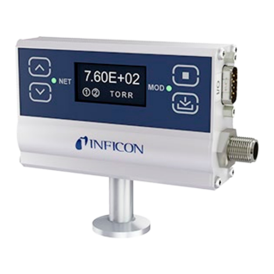
® tioning required to turn a convection vacuum gauge into a com- plete measuring instrument. This version of the PGE500 pro- vides a DeviceNet interface as well as two process control set- point relays. Additionally a built-in OLED digital display provides the measured pressure values and provides for a convenient user interface for setup and operation of the vacuum gauge. -
Page 10: Specifications
Specifications Measurement range 1.3×10 … 1333 mbar 1×10 … 1000 Torr 1.3×10 Pa … 133 kPa Accuracy - N (typical) 1×10 … 1×10 Torr 0.1 mTorr resolution 1×10 … 400 Torr ±10% of reading 400 … 1000 Torr ±2.5% of reading Repeatability - N (typical) ±2% of reading... - Page 11 Relative humidity 0 … 95%, non-condensing Operating altitude up to 2500 m (8200 ft.) Storage altitude up to 12500 m (41000 ft.) Mounting orientation horizontal recommended (orientation has no effect on measurements below 1.3 mbar (1 Torr)) DeviceNet Interface Device type vacuum gauge/pressure gauge device Adjustable parameters...
-
Page 12: Dimensions
Dimensions Fitting Dimension A (inch) DN 16 ISO-KF 29.5 (1.16) DN 25 ISO-KF 29.5 (1.16) DN 40 ISO-KF 29.5 (1.16) DN 16 CF-R (1.34) DN 40 CF-R (1.34) 4 VCR female 43.7 (1.72) 8 VCR female 40.9 (1.61) 1/8" NPT male 21.8 (0.86) tinb60e1... -
Page 13: Important Safety Information
Important Safety Information INFICON has designed and tested this product to provide safe and reliable service, provided it is installed and operated within the strict safety guidelines provided in this manual. Please read and follow all warnings and instructions. WARNING To avoid serious injury or death, follow the safety informa- tion in this document. -
Page 14: Safety Precautions - Service And Operation
Do not modify this product or substitute any parts without au- thorization of qualified INFICON service trained personnel. Re- turn the product to an INFICON qualified service and repair cen- ter to ensure that all safety features are maintained. Do not use this product if unauthorized modifications have been made. -
Page 15: Electrical Conditions
Do not use if the unit has been dropped or the enclosure has been damaged. Contact INFICON for return authorization and instructions for returning the product to INFICON for evaluation. Electrical Conditions WARNING! When high voltage is present in any vacuum... -
Page 16: Proper Equipment Grounding
WARNING! Hazardous voltages that could seriously in- jure or cause death are present in many vacuum processes. Verify that the vacuum port on which the PGE500 vacuum gauge module is mounted is electrically grounded. Consult a qualified Electrician if you are in doubt about your equipment grounding. -
Page 17: Overpressure And Use With Hazardous Gases
The PGE500 vacuum gauge module is not intended for use at pressures above 20 psia (1000 Torr); DO NOT exceed 35 psig (<2½ bars) pressure inside the sensor. If your chamber goes to... -
Page 18: Gases Other Than Nitrogen / Air
Installation Mechanical Installation Mount the PGE500 as close as possible to the pressure you want to measure. Long or restricted, small diameter tubing will create a pressure difference between your process chamber and the gauge. - Page 19 Mounting the PGE500 too close to a gas source inlet may also cause measurement and control instability. Do not mount the PGE500 near a source of heating or cooling, such as heaters or air conditioning vents. Mount the PGE500 with its main (long) axis horizontal (see dia- gram below).
- Page 20 Do not mount the PGE500 where it will be subjected to exces- sive vibration. Vibrations may cause unstable readings, measu- rement errors and possible mechanical stress to components in the PGE500.
-
Page 21: Electrical Installation
- NPT fittings: When connecting the device using a NPT fitting, apply a thread sealant or wrap the threaded portion of the tubing with one-and-a-half to two wraps of pipe thread seal tape such as PTFE (Teflon®) tape and hand tighten the gauge into the gauge port. -
Page 22: Electrical Connections
3.2.2 Electrical Connections A good recommended practice is to remove power from any cable prior to connecting or disconnecting it. 9-pin D-sub Connector pinout Pin no. Pin description Relay 2 Normally Open Relay 2 Common Relay 2 Normally Closed No Connection Relay 1 Common Relay 1 Normally Closed Relay 1 Normally Open... -
Page 23: Setup And Operation
Setup and Operation User Interface Basics The setup and programming is done via the four programming- keys located on the front panel of the PGE500. During program- ming of the gauge, the display will identify what function each key represents. -
Page 24: Devicenet And Module Status Leds
DeviceNet and Module Status LEDs In addition to a built-in display the PGE500 is provided with two status LED indictors as shown below. The LED indicator marked NET represents the DeviceNet network status. The LED indica- tor marked MOD represents the gauge module (PGE500) status. -
Page 25: Devicenet Setup Switches
NET Status LED: Meaning no power to the gauge gauge is not connected to the network duplicate MAC ID check is not complete gauge not able to communicate on the DeviceNet network check for duplicate MAC ID or network off flashing I/O connection(s) in the timed out state flashing... -
Page 26: Data Rate Switch Setting
Switch marked "LSD" represents the least significant digit of the address (second digit) and it can be set to any number from 0 to 9. If the Node Address switch is set to PGM, the PGE500 uses the MAC ID setting that is sent from the network master. The... -
Page 27: Initial Setup
network master is achieved. The NET status LED will then become solid green indicating the connection is complete. Initial Setup Two of the most important steps for the initial setup of the gauge are to set atmosphere (SET ATM) set zero (SET VAC) and as described in the Programming section 4.6.4 below. -
Page 28: Factory-Set Default Parameters
ATM and VAC and reprogram other parameters as required. Factory-Set Default Parameters The following is a summary of all factory-set default values in the PGE500 display menu. DISPLAY • UNITS: [Factory default = TORR] • CNTRAST: [Factory default = 6] •... - Page 29 • GAUGE INFO [Factory default MSN: Actual Module Serial Number GSN: Actual Gauge Serial Number FW: Firmware version of device CALIBRATION • SET ATM [Factory default = SET TO 760] • SET VAC [Factory default = SET TO ZERO] DFAULTS •...
-
Page 30: Programming
Programming This section provides detailed information on programming and configuration of various menus and submenus of the device. To begin programming, press the MENU key to access the top-level menus shown below: MAIN MENU Cursor ▶ DISPLAY Use the UP and STATUS DOWN keys to move DFAULTS... - Page 31 Note - Factory default setting of 6 optimizes display life. SCRN SVR [Factory default = ON] The PGE500 uses an OLED type display which over an exten- ded period of time can start to show divergence between pixels that are on at all times verses pixels that are not. This could result in pixels exhibiting a burned-in effect.
-
Page 32: Status
measured pressure value from 1000 to 1 Torr will be displayed in units of measure in Torr and any pressure values below 1 Torr will be displayed in mTorr. 4.6.2 STATUS The following menu choices allows the user to see any pending error conditions as well as gauge identification information. -
Page 33: Calibration
2) If you are at sea level you may simply select "SET TO 760" if the units of measure selected is in Torr (SET TO 1.01E+03 if using mbar or SET TO 1.01E+05 if using Pa). PGE500 re- sponds with message ATM SET confirming atmosphere has been successfully set. -
Page 34: Relays
INFICON advises that you first determine if the "span" (SET ATM) adjustment of your measurement device is set properly before setting the "zero" (SET VAC) adjustment. It is good prac- tice to perform the sequence of checking and adjusting ATM (span) then VAC (zero) and then, finally re-checking the ATM setting to ensure the instrument has been properly set. - Page 35 This setpoint corresponds to the turn on point for Relay 1. Relay 1 will turn on when the pressure drops below this setting. If you are unable to increase the value of LO TRIP (PGE500 respond- ing with message "LO MORE THAN HI"), you must first access the HI TRIP menu below and increase that value to a number higher than the value of the LO TRIP you are trying to set.
- Page 36 HI TRIP [Factory default = 7.50 E+02 TORR] Same instructions as relay 1 HI TRIP above. TEST RELAYS This allows the user to manually toggle the relays on and off to test for correct external circuit wiring and ensure polarity is as desired.
-
Page 37: Using The Gauge With Different Gases
Since different gases, and mixtures, have different thermal con- ductivities, the indicated pressure readings and outputs will also be different. INFICON convection gauges (and most other ther- mal conductivity gauges) are calibrated using nitrogen (N When a gas other than N... - Page 38 Under normal conditions the voltages and currents in INFICON convection gauges are too low to cause ignition of flammable gases.
- Page 39 The X-axis is the pressure reading indicated by the convection gauge under test. This chart shows readings for an INFICON convection gauge (CVG) and Granville-Phillips® Convectron® gauge to illustrate that the difference in the response for both of these types of gauges is virtually indistinguishable.
-
Page 40: Display
attempting to increase the reading up to 760 Torr, you will over pressurize your chamber which may present a hazard. Example C: If the gas is helium (He), the gauge will over pres- sure (OP) when pressure reaches about 10 Torr true pressure and opening the chamber to atmosphere prematurely may pre- sent other hazards for both people and product. - Page 41 tinb60e1 (2020-07)
- Page 42 tinb60e1 (2020-07)
- Page 43 tinb60e1 (2020-07)
-
Page 44: Display - Mbar
Notes: OP = Overpressure (Display shows PR OVER PRS) Examples: 1) Using nitrogen (N ), pressure display shows 1.00E+01 Torr. True pressure of nitrogen is 1.00E+01 Torr. 2) Using argon (Ar), pressure display shows 8.83E+0 Torr. True pressure of argon is 1.00E+02 Torr. 3) Using oxygen (O ), pressure display shows 4.86E-01 mTorr. - Page 45 tinb60e1 (2020-07)
- Page 46 tinb60e1 (2020-07)
- Page 47 tinb60e1 (2020-07)
-
Page 48: Devicenet Operation
), pressure display shows pressure measurement of 1.29E-02 mBAR. True pressure of O2 is 1.33E-02 mBAR. DeviceNet Operation Supported DeviceNet Objects for ODVA compliance The PGE500 supports all standard DeviceNet objects, attributes and services required for ODVA certification. Class Object Identity Message Router... -
Page 49: Supported Devicenet Objects Compliant With Semi Guidelines
3 Value only. Two instances are supported indicating the state of the Trip Points. Configuring the DeviceNet switches • Turn off power to the PGE500 by disconnecting the 5-pin DeviceNet Micro Connector from the network. • Set the MAC ID Switches (Node Address Switches) to the correct address (0-63). -
Page 50: Allocating Devicenet Connections To The Pge500
Allocating DeviceNet connections to the PGE500 The master must use a DeviceNet object command to open Polled and Explicit connections. Other connection types are not supported. The example below allocates polled and explicit connections. Service 4B hex DeviceNet Class Instance... -
Page 51: Configuring Polled I/O Data Format
Configuring Polled I/O data format The PGE500 can provide input polled pressure data in UINT in- teger or REAL floating point formats, with or without BYTE status data. If a polled connection is established before this message, remove and reestablish the connection. The status byte indi- cates Warning in bit 5 (reading lower than zero vacuum, calibra- tion needed) and Alarm in bit 1 (sensor failure). -
Page 52: Uint 2 Byte Integer Pressure
UINT 2 byte integer pressure The integer value is proportional to the pressure measured by the PGE500. The table below provides the conversion from inte- ger to Torr pressure. Pressure Integer value Pressure Integer value 0.0001 5986 0.001 6246 0.01 6523 0.015... - Page 53 As a node in the network, the PGE500 produces data on the network with a unique address. All devices on the network that need the data listen for messages. When other devices on the network recognize the PGE500's unique address, they use...
-
Page 54: Standard Objects
7.9.1 Standard Objects There is a single instance of the Identity Object for the PGE500. No class attributes are supported. All of the instance attributes are contained in ROM or EEPROM. 7.9.1.1 Identity Object 0Ehex 1 None UINT Vendor Open... -
Page 55: Devicenet Object
7.9.1.2 DeviceNet Object There is a single instance of the DeviceNet Object for the PGE500. No class attributes are supported. 0Ehex 3 None USINT Get node address, range Open 0-63 0Ehex 3 None USINT Get baud rate, range 0-2 Open... -
Page 56: Connection Object - Explicit Message Connection
7.9.1.3 Connection Object - Explicit Message Connection There are two instances of the Connection Object PGE500. In- stance #1 is assigned to the Explicit Message Connection. In- stance #2 is assigned to the Polled I/O Connection. The follow- ing two tables below show the attributes and the predefined values of each. -
Page 57: Connection Object - Polled I/O Data
0Ehex 5 0Fhex None 00 00 UINT Get consumed Open connection path length 0Ehex 5 10hex None EPATH Get consumed Open connection path Connection Object - Explicit Message Connection 7.9.1.4 Connection Object - Polled I/O Data 0Ehex 5 None USINT Get state of the object, Open range 0-5 0Ehex 5... -
Page 58: Discrete Output Point Object
10hex 5 0Dhex 06 00 Success UINT Set produced connection Open path length 0Ehex 5 0Ehex None EPATH Get produced connection Open path 10hex 5 0Ehex 01 Success EPATH set produced connection Open path 0Ehex 5 0Fhex None 06 00 UINT Get consumed connection Open... -
Page 59: S-Device Supervisor Object
None E54-0997 SHORT SEMI Standard Open STRING Revision Level 0Ehex 30hex 1 None INFICON SHORT Manufacturer's Open STRING Name 0Ehex 30hex 1 None PGE500 SHORT Manufacturer's Open STRING Model Number 0Ehex 30hex 1 None V1.01 SHORT Software Revision Open STRING Level... -
Page 60: S-Analog Sensor Object
7.9.1.7 S-Analog Sensor Object The S-Analog Sensor Object models the acquisition of a reading from the convection sensor in the PGE500. The Heat Transfer Gauge Subclass is implemented here. Values in the Device Data column are examples. 0Ehex 31hex 1... -
Page 61: S-Gas Calibration Object
7.9.1.8 S-Gas Calibration Object The S-Gas Calibration Object affects the behavior of an asso- ciated S-Analog Sensor object instance; a device profile will show a relationship between these two objects where an S-Gas Calibration Object is used. 0Ehex 34hex 1 None 0D 00 UINT Gas Standard Number = Open... -
Page 62: Trip Point Object
7.9.1.9 Trip Point Object The Trip Point Object models the action of trip points for the PGE500, corresponding to the set point relays. There are two instances of this object supported by this device. Values in the Device Data column are examples. -
Page 63: Service
Service Calibration Every INFICON module is calibrated prior to shipment using ni- trogen (N ). However, you can calibrate the instrument by adjust- ing zero (vacuum) and span (atmosphere) using the procedure described previously in section 4.6.4 titled "Calibration". Zero and span (atmosphere) calibration affect the displayed value and the output signal. -
Page 64: Troubleshooting
Troubleshooting tinb60e1 (2020-07) - Page 65 tinb60e1 (2020-07)
-
Page 66: Contamination
The standard gold plated tungsten sensor used in the INFICON convection gauge is offered for use with air and inert gases such as N , argon, etc. INFICON also offers platinum sen- sors for applications not compatible with gold plated tungsten. - Page 67 B) Oil, Condensation, Coatings, and Particles If the failure is due to an accumulation of material in the gauge, we may be able to restore your gauge or module by cleaning. Contamination may be as simple as condensed water, or as difficult as solid particles.
-
Page 68: Module And Sensor Replacement
Module and sensor replacement The sensor in the PGE500 can be replaced in the field. Once a new sensor is installed the procedure described in section 4.6.4 must be followed to set atmosphere and zero. - Page 69 Remove all 8 Torx screws from both side panels of the enclosure. Remove the back panel by lifting it off from the enclosure. tinb60e1 (2020-07)
- Page 70 Remove the side panel that covers the three mechanical switches. Note how far the pins protrude through the bridge PCB by measuring dimension A show below. This dimension will be used for proper reinstallation of the sensor assembly. Bridge PCB Sensor tinb60e1...
- Page 71 Remove the bridge PCB from the assembly. Remove the sensor from the assembly by pulling it up and out of the enclosure assembly. tinb60e1 (2020-07)
- Page 72 Push pins of new sensor through the holes in the Bridge PCB. Set Dimension A as previously measured in step 4. GENTLY lift the CPU PCB and install the bridge PCB / sen- sor assembly into the CPU PCB. Lift CPU PCB tinb60e1 (2020-07)
- Page 73 After reinstalling the bridge PCB / sensor into the CPU PCB reinstall the side panel. Reinstall the back panel … tinb60e1 (2020-07)
-
Page 74: Factory Service And Support
If you need help setting up, operating, troubleshooting, or obtaining a return materials authorization number (RMA number) to return the module for diagnosis, please contact us during normal business hours Monday through Friday, at +423 / 388 3111. Or e-mail us at reachus@inficon.com. tinb60e1 (2020-07) -
Page 75: Returning The Product
Contaminated products (e.g. radioactive, toxic, caustic or microbiological hazard) can be detrimen- tal to health and environment. Products returned to INFICON should preferably be free of harmful substances. Adhere to the forward- ing regulations of all involved countries and for-... - Page 76 WARNING Substances detrimental to the environment Products or parts thereof (mechanical and electric components, operating fluids etc.) can be detrimen- tal to the environment. Dispose of such substances in accordance with the relevant local regulations. Separating the components After disassembling the product, separate its components ac- cording to the following criteria: •...
-
Page 77: Spare Parts
• all information on the product nameplate • description and ordering number according to the spare parts list Gold Plated Tungsten Sensor Ordering no. PGE500 Spare Sensor KF 16, W 352-550 PGE500 Spare Sensor KF 25, W 352-551 PGE500 Spare Sensor KF 40, W... -
Page 78: Eu Declaration Of Conformity
EU Declaration of Conformity We, INFICON, hereby declare that the equipment mentioned below comply with the provisions of the following directives: • 2014/30/EU, OJ L 96/79, 29.3.2014 (EMC Directive; Directive relating to electromagnetic compatibility) • 2011/65/EU, OJ L 174/88, 1.7.2011 (RoHS Directive;... - Page 79 Notes tinb60e1 (2020-07)
- Page 80 LI–9496 Balzers Liechtenstein Tel +423 / 388 3111 Fax +423 / 388 3700 reachus@inficon.com www.inficon.com Original: English...
Need help?
Do you have a question about the PGE500 and is the answer not in the manual?
Questions and answers