
Related Manuals for Inficon BPG400


Summary of Contents for Inficon BPG400
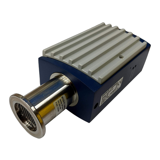
- Page 1 Operating Manual Bayard-Alpert Pirani Gauge BPG400 BPG400-SD BPG400-SP tina03e1 (0206)
-
Page 2: Product Identification
KF vacuum connection. They apply to other vacuum connections by analogy. In illustrations that apply to all types of the BPG400 gauge family, the gauge with part number 353-500 is shown. All BPG400 versions are shipped with an instruction sheet (® & [8]). BPG400-SD and BPG400-SP come with a supplementary instruction sheet describing the field- bus interfaces and the switching functions (®... -
Page 3: Functional Principle
Pirani measurement system only below the switching threshold of 2.4×10 mbar (to prevent filament burn-out). It is switched off when the pressure exceeds 3.2×10 mbar. Trademarks DeviceNet™ Open DeviceNet Vendor Association, Inc. tina03e1 (0206) BPG400 v1.om... -
Page 4: Table Of Contents
3.1.3 Using the Optional Baffle 3.1.3.1 Installing the Baffle 3.1.3.2 Replacing the Baffle 3.2 Electrical Connection 3.2.1 Use With INFICON VGC103 or VGC40x Vacuum Gauge Controller 3.2.2 Use With Other Controllers 3.2.2.1 Making an Individual Sensor Cable 3.2.2.2 Making a DeviceNet Interface Cable (BPG400-SD) 3.2.2.3 Making a Profibus Interface Cable (BPG400-SP) - Page 5 A: Relationship Output Signal – Pressure B: Gas Type Dependence C: Literature Declaration of Contamination For cross-references within this document, the symbol (® 2 XY) is used, for cross- references to further documents and data sources, the symbol (® & [Z]). tina03e1 (0206) BPG400 v1.om...
-
Page 6: Safety
1.2 Personnel Qualifications Skilled personnel All work described in this document may only be carried out by persons who have suitable technical training and the necessary experience or who have been instructed by the end-user of the product. tina03e1 (0206) BPG400 v1.om... -
Page 7: General Safety Instructions
Communicate the safety instructions to all other users. 1.4 Liability and Warranty INFICON assumes no liability and the warranty becomes null and void if the end- user or third parties · disregard the information in this document ·... -
Page 8: Technical Data
0 V/+24 VDC, active high (control via RS232 ® 2 32) Duration max. 3 min, followed by automatic stop In degas mode, BPG400 gauges keep supplying measurement values, however their tolerances may be higher than during normal operation. Output signal Output signal (measuring signal) 0 …... - Page 9 The gauge is protected against reversed polarity of the supply voltage. Sensor cable For reasons of compatibility, the expression "sensor cable" is used for all BPG400 versions in this document, although the pressure reading of the gauges with fieldbus interface (BPG400-SD and BPG400-SP) is normally transmitted via DeviceNet or Profibus.
- Page 10 (Adjustable via hexadecimal "ADDRESS", "MSD", "LSD" switches) Profibus connection D-Sub, 9 pins, female Cable Shielded, special Profibus cable (® 2 25 and & [5]) Cable length, system wiring According to Profibus specifications (® & [7], [5]) tina03e1 (0206) BPG400 v1.om...
- Page 11 (year's mean / during 60 days) £65 / 85% (no condensation) indoors only altitude up to 2000 m NN Type of protection IP 30 Dimensions Part numbers 353-500 353-501 353-505 (353-507) 4-40UNC 2B DN 25 ISO-KF 353-500 353-501 tina03e1 (0206) BPG400 v1.om...
- Page 12 Gauges with DeviceNet connector are 14 mm longer. The other dimensions of housing and vacuum connection are identical. Part numbers 353-507 353-508 Weight 353-500, 353-501 285 g 353-502, 353-503 550 g 353-505, 353-507 430 g 353-506, 353-508 695 g tina03e1 (0206) BPG400 v1.om...
-
Page 13: Installation
The sensor can be baked at up to 150 °C. At temperatures exceeding 50 °C, the electronics unit has to be removed (® 2 15) or an extension (Option ® 2 47) has to be installed (® 2 16). tina03e1 (0206) BPG400 v1.om... - Page 14 When installing the gauge, allow for installing/deinstalling the connectors and accommodation of cable loops. If you are using a gauge with display, make sure easy reading of the display is possible. The gauge is now installed. tina03e1 (0206) BPG400 v1.om...
-
Page 15: Removing And Installing The Electronics Unit
Remove the electronics unit without twisting it. Removal of the electronics unit is completed. Installing the electronics unit ΠPlace the electronics unit on the sensor (3) (be careful to correctly align the pins and notch (4)). tina03e1 (0206) BPG400 v1.om... -
Page 16: Installing The Optional Extension
Allen key, size 1.5 mm Procedure Œ Remove the electronics unit (2) (® 2 15). Slide the sensor (3) into the extension (6) to the mechanical stop (be careful to correctly position the pins and notch (4)). tina03e1 (0206) BPG400 v1.om... -
Page 17: Using The Optional Baffle
Touching the product or parts thereof with bare hands increases the desorption rate. Always wear clean, lint-free gloves and use clean tools when working in this area. Required tools / material · Baffle (® 2 47) · Pointed tweezers · Pin (e.g. pencil) tina03e1 (0206) BPG400 v1.om... - Page 18 Carefully remove the grid with tweezers. Carefully place the baffle onto the sensor opening. Ž Using a pin, press the baffle down in the center until it catches. The baffle is now installed (Installation of the gauge ® 2 13). tina03e1 (0206) BPG400 v1.om...
-
Page 19: Replacing The Baffle
Required tools / material · New baffle (® 2 47) · Screwdriver No 1 · Pin (e.g. pencil) Procedure Œ Carefully remove the baffle with the screwdriver. Place new baffle carefully onto the sensor opening. tina03e1 (0206) BPG400 v1.om... -
Page 20: Electrical Connection
The new baffle is now installed (Installation of the gauge ® 2 13). 3.2 Electrical Connection 3.2.1 Use With INFICON If the gauge is used with an INFICON VGC103 or VGC40x controller, a corre- VGC103 or VGC40x sponding sensor cable is required (® 2 47). The sensor cable permits supplying... -
Page 21: Use With Other Controllers
Plug the sensor connector into the gauge and secure it with the locking screws. Connect the other end of the sensor cable to the INFICON controller and secure it. The gauge can now be operated with the VGC103 or VGC40x controller. - Page 22 Pin 12 Signal common, GND Pin 13 RS232C, TxD Pin 14 RS232C, RxD Pin 15 Shielding, housing, GND Pins 1, 3, 4, 6, 9 and 11 are not connected internally. D-Sub, 15 pins female, soldering side tina03e1 (0206) BPG400 v1.om...
- Page 23 Sensor cable connection BPG400-SD, BPG400-SP BPG400-SD, BPG400-SP Threshold value, SP A Threshold value, SP B SP A SP B RS232 Degas Degas 1.25 AT Measuring signal 42 kW Identification Electrical connection Pin 1 Relay Switching function A, common Pin 2 Signal output (measuring signal) 0 …...
-
Page 24: Making A Devicenet Interface Cable (Bpg400-Sd)
The gauge can now be operated via analog and RS232C interface. 3.2.2.2 Making a DeviceNet For operating BPG400-SD via DeviceNet, an interface cable conforming to the Interface Cable DeviceNet standard is required. (BPG400-SD) If no such cable is available, make one according to the following indications. -
Page 25: Making A Profibus Interface Cable (Bpg400-Sp)
Lock the DeviceNet (and sensor) cable connector. The gauge can now be operated via DeviceNet interface ( ® 2 35). 3.2.2.3 Making a Profibus For operating BPG400-SP via Profibus, an interface cable conforming to the Interface Cable Profibus standard is required. -
Page 26: Using The Optional Power Supply (With Rs232C Line)
The gauge can now be operated via Profibus interface ( ® 2 37). 3.2.3 Using the Optional Power The optional 24 V power supply ( ® 2 47) allows RS232C operation of the BPG400 Supply (With RS232C gauge with any suitable instrument or control device (e.g. PC). - Page 27 RS232C Power supply Mains BPG400 Ž Connect the power supply to the mains. Turn the power supply on. The gauge can now be operated via RS232C interface ( ® 2 32). tina03e1 (0206) BPG400 v1.om...
-
Page 28: Operation
4 Operation 4.1 Measuring Principle, The BPG400 vacuum gauges consist of two separate measuring systems (hot cathode Bayard-Alpert (BA) and Pirani). Measuring Behavior Bayard-Alpert The BA measuring system uses an electrode system according to Bayard-Alpert which is designed for a low x-ray limit. -
Page 29: Operational Principle Of The Gauge
The bridge voltage U is a measure for the gas pressure and is further processed electronically (linearization, conversion). Measuring range The BPG400 gauges continuously cover the measuring range 5×10 mbar … 1000 mbar. · The Pirani constantly monitors the pressure. -
Page 30: Degas
700 °C by electron bombardment. Depending on the application, this function can be activated manually by a switch or automatically by the system control via a digital interface. The BPG400 automatically terminates the degas process after 3 minutes, if it has not been stopped before. -
Page 31: Error Display
Error display no error (green background illumination) Pirani sensor warning (red background illumination) Pirani sensor error (red background illumination) BA sensor error (red background illumination) Internal data connection failure (red background illumination) tina03e1 (0206) BPG400 v1.om... -
Page 32: Rs232C Interface
Caution Caution: data transmission errors If the gauge is operated with the INFICON VGC103 or VGC40x Vacuum Gauge Controller (RS232C) and a fieldbus interface at the same time, data transmission errors may occur. - Page 33 ((high byte × 256 + low byte) / 4000 - 12.5) mbar = 10 ((high byte × 256 + low byte) / 4000 - 12.625) Torr = 10 ((high byte × 256 + low byte) / 4000 - 10.5) tina03e1 (0206) BPG400 v1.om...
-
Page 34: Input String (Receive)
Set the unit Pa in the display Power-failure-safe storage of current unit Switch degas on (switches itself off after 3 minutes) Switch degas off before 3 minutes Only low order byte of sum (high order byte is ignored). tina03e1 (0206) BPG400 v1.om... -
Page 35: Devicenet Interface (Bpg400-Sd)
Two adjustable switching functions are integrated in BPG400-SD. The corre- sponding relay contacts are available at the sensor cable connector ( ® 2 8, 23, 38). The basic sensor and sensor electronics of all BPG400 gauges are identical. Caution Caution: data transmission errors If the gauge is operated via RS232C interface and DeviceNet interface at the same time, data transmission errors may occur. -
Page 36: Data Rate Setting
Communication error. The gauge has detected an error that im- pedes communication via the network (e.g. two identical node addresses (MAC IC) or "Bus-off") Electrical connections The gauge is connected to the DeviceNet system via the 5-pin DeviceNet con- nector ( ® 2 24). tina03e1 (0206) BPG400 v1.om... -
Page 37: Profibus Interface (Bpg400-Sp)
BPG400-SP are described in detail in the separate Communication Protocol ( ® & [2]). 4.8.2.1 Operating Software For operating the gauge via Profibus, prior installation of the BPG400 specific GSD file is required on the bus master side. This file can be downloaded via internet ( ® & [3]). -
Page 38: Switching Functions (Bpg400-Sd, Bpg400-Sp)
4.9 Switching Functions The gauges BPG400-SD and BPG400-SP have two independent, manually settable switching functions. Each switching function has a floating normally open (BPG400-SD, relay contact. The relay contacts are accessible at the sensor cable connector BPG400-SP) ( ® 2 23). - Page 39 However, a functional check of the switching functions (On/Off) can be made with one of the following methods: · Reading the status via fieldbus interface ® & [1] for BPG400-SD, ® & [2] for BPG400-SP. · Measurement of the relay contacts at the sensor cable connector with a ohmmeter/continuity checker ( ®...
-
Page 40: Deinstallation
Depending on the programming of the superset controller, faults may occur or error messages may be triggered. Follow the appropriate shut-down and starting procedures. Take gauge out of operation. Ž Disconnect all cables from the gauge. Remove gauge from the vacuum system. tina03e1 (0206) BPG400 v1.om... - Page 41 Place the protective lid. The gauge is now deinstalled. tina03e1 (0206) BPG400 v1.om...
-
Page 42: Maintenance, Repair
· when the vacuum system is vented, the digital value received by the bus con- troller of the fieldbus (DeviceNet or Profibus) reaches its maximum before the measured pressure has reached atmosphere. tina03e1 (0206) BPG400 v1.om... -
Page 43: Zero Point Adjustment
Pin approx. ø1.3 × 50 mm (e.g. a bent open paper clip) Procedure Gauges BPG400-SD and -SP are mechanically slightly different from the BPG400. The adjustment opening of BPG400-SD and -SP is on one side of the gauge housing. However, the adjustment procedure is the same for all gauge versions. Œ... -
Page 44: What To Do In Case Of Problems
· Spare sensor (if the sensor is faulty) Troubleshooting (BPG400) The output signal is available at the sensor cable connector (Pin 2 and Pin 12). In case of an error, it may be helpful to just turn off the mains supply and turn it on again after 5 s. - Page 45 All of the above faults can only be remedied by replacing the sensor ( ® 2 46). Troubleshooting Error diagnosis of fieldbus gauges BPG400-SD and -SP can only be performed as (BPG400-SD, BPG400-SP) described above for the basic sensor and sensor electronics. Diagnosis of the fieldbus interface can only be done via the superset bus controller ( ®...
-
Page 46: Replacing The Sensor
Deinstall the gauge ( ® 2 40). Deinstall the electronics unit from the faulty sensor and mount it to the new sensor ( ® 2 15). Ž Adjust the gauge ( ® 2 42). The new sensor is now installed. tina03e1 (0206) BPG400 v1.om... -
Page 47: Options
Connection elements, seals, accessories See INFICON sales literature and data sources for controllers and our range of sensor cables ( ® & [10]). Since there is a vast variety of individual configurations and applications, please refer to the specific information for your individual configuration ( ®... -
Page 48: Returning The Product
Contaminated products (e.g. radioactive, toxic, caustic or biological hazard) can be detrimental to health and environment. Products returned to INFICON should preferably be free of harmful substances. Adhere to the forwarding regulations of all involved countries and forwarding companies and enclose a duly completed declaration of contamination ( ®... -
Page 49: Appendix
U = 0.75 × (log p - c) + 7.75 where [mbar] [Pa] [Torr] -0.125 Conversion curve Pressure p [mbar] 1E+04 1E+03 1E+02 1E+01 1E+00 1E–01 1E–02 1E–03 1E–04 1E–05 1E–06 1E–07 1E–08 1E–09 1E–10 10.0 Measuring signal U[V] tina03e1 (0206) BPG400 v1.om... -
Page 50: B: Gas Type Dependence
Inadmissible range Gas Type Dependence Indication range Pressure indicated (gauge adjusted for air, Pirani-only mode) above 10 mbar p (mbar) He Ne Indication range Freon 12 above 10 mbar) –1 vapor –2 –3 –3 –2 –1 (mbar) tina03e1 (0206) BPG400 v1.om... - Page 51 Calibration factor C Air, O , CO, N2 (The above calibration factors are mean values.) A mixture of gases and vapors is often involved. In this case, accurate determination is only possible with a partial-pressure measuring instru- ment. tina03e1 (0206) BPG400 v1.om...
-
Page 52: C: Literature
Literature & [1] www.inficon.com Communication Protocol DeviceNet™ BPG400-SD tira03e1 INFICON AG, LI–9496 Balzers, Liechtenstein & [2] www.inficon.com Communication Protocol Profibus BPG400-SP tira36e1 INFICON AG, LI–9496 Balzers, Liechtenstein & [3] www.inficon.com Product descriptions and downloads INFICON AG, LI–9496 Balzers, Liechtenstein & [4] www.odva.org... -
Page 53: Declaration Of Contamination
Post code, place Phone E-mail Name Date and legally binding signature Company stamp This form can be downloaded Copies: from our website. Original for addressee - 1 copy for accompanying documents - 1 copy for file of sender tina03e1 (0206) BPG400 v1.om... - Page 54 Notes tina03e1 (0206) BPG400 v1.om...
- Page 55 Notes tina03e1 (0206) BPG400 v1.om...
- Page 56 LI–9496 Balzers Liechtenstein Tel +423 / 388 3111 Fax +423 / 388 3700 reach.liechtenstein@inficon.com Original: German tina03d1 (0206) www.inficon.com t i na03e1...
Need help?
Do you have a question about the BPG400 and is the answer not in the manual?
Questions and answers