Advertisement
Quick Links
INSTRUCTION SHEET
Easy Rate™ Sensor
Introduction
This instruction sheet describes the proper installation, operation, maintenance, and
repair of the Easy Rate single and dual sensors.
This product has a warranty of one year from the date of purchase. This warranty covers
defects of materials or workmanship under normal proper use and service. Refer to the
INFICON website for warranty details. The batch number of the sensor can be found on
the packaging label. It is important to document this number for any necessary warranty
claims.
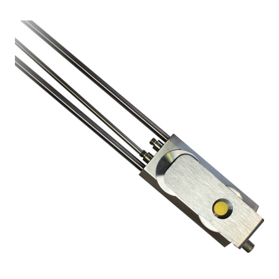
Figure 1 Easy Rate Sensors
PN 074-677-P1A
1 of 13
Advertisement

Related Manuals for Inficon Easy Rate ERD E1 Series


Summary of Contents for Inficon Easy Rate ERD E1 Series
- Page 1 Refer to the INFICON website for warranty details. The batch number of the sensor can be found on the packaging label. It is important to document this number for any necessary warranty claims.
-
Page 2: Installation
Easy Rate Sensor Installation Install the sensor as far as possible from the evaporation source (a minimum of 25.4 cm (10 in.)) while still being in a position to accumulate thickness at a rate proportional to accumulation on the substrate. Figure 2 shows proper and improper methods of installing sensors. - Page 3 Easy Rate Sensor NOTE: In many cases, installing multiple sensors to monitor one source can improve thickness accuracy for the product, using a feature known as multiple sensor averaging. The installation requirements for multiple sensors are the same as for a single sensor installation, and the locations chosen should be as defined in Figure 2.
- Page 4 Easy Rate Sensor Vacuum rated connectors are recommended for use between the sensor and the feedthrough to speed maintenance. If brazing adapters are to be used, attach them to the sensor water-cooling tubes and to the air tube prior to connection to the feedthrough.
- Page 5 When deactivated, the shutter should completely cover the crystal opening. Repositioning of the shutter or actuator may be required to achieve optimum on/off positioning. If operation is found to be impaired, contact INFICON. (See Figure Figure 4 Shutter completely covering the crystal opening NOTE: A solenoid valve (PN 750-420-G1) is required with any new shutter installation.
- Page 6 Easy Rate Sensor Actuator Installation If installing an actuator on an existing standard single or dual sensor, the actuator front face should align as shown with the sensor body. (See Figure 5.) Installation of the sensor shutter on existing equipment requires either a Single Shutter Assembly (PN 784-209-G1) or a Dual Shutter Assembly (PN 784-210-G1).
-
Page 7: Operation
76.2 cm (30 in.) for In-vacuum cable PN 783-500-024, which is used in the following Easy Rate Sensor configurations: ERS-X2XE1XX and ERD-X2E1XX NOTE: Refer to the Easy Rate Sensor data sheet (located at inficon.com) for information on part number configuration. The cable length from the crystal to the oscillator should not exceed 91.44 cm (36 in.) unless a ModeLock instrument... -
Page 8: Maintenance
Easy Rate Sensor ™ Grasp the edge of the new crystal with a clean pair of Teflon tweezers. Orient the crystal so the patterned electrode is facing up. Gently insert the edge of the crystal into the crystal holder pushing aside the spring contacts until the crystal is seated evenly and securely in the crystal holder. - Page 9 Repairs to this sensor can be done in the field by an electrical technician at the risk and responsibility of the sensor owner. NOTE: Beyond the warranty period, this sensor is not serviced by INFICON. WARNING INFICON is not responsible for any damage or loss of property that may occur during a sensor repair.
- Page 10 Holder Finger Spring Easy Rate Sensor ....PN 784-405-P1 Crystal Holder Assembly Easy Rate Sensor ... PN 784-204-G1 Items not provided by INFICON: 22 AWG, Buss Wire, Solid, Tin Coated Copper ™...
- Page 11 Easy Rate Sensor ™ Tools: Soldering iron, adjustable wrench, Teflon tweezers, torque screwdriver or wrench Grasp the microdot connector by the flat sides using an adjustable wrench and loosen it. (See Figure Figure 8 Microdot connector NOTE: If the wire inside is still intact, the connection will break as the connector comes loose.
- Page 12 Easy Rate Sensor ™ Using Teflon tweezers, gently pry the crystal holder spring out of the sensor body. (See Figure 10.) Figure 10 Crystal holder spring NOTE: Move the spring circularly until the gap between the two ends is found and pry it out from there.
- Page 13 Install the holder spring and crystal holder assembly to complete the repair. ® www.inficon.com re achus@inficon.com Due to our continuing program of product improvements, specifications are subject to change without notice. All trademarks are the property of their respective owners.
Need help?
Do you have a question about the Easy Rate ERD E1 Series and is the answer not in the manual?
Questions and answers