Advertisement
L
D
T
ittfinski
aten
echnik (
Operating Instruction
4-fold turnout decoder
with possible external power supply
from the Digital-Professional-Series !
S-DEC-4-DC-G
>> finished module in a case <<
Compatible to the DCC-Format:
(e.g. Lenz Digital Plus, Arnold-, Märklin-Digital=, Intellibox,
TWIN-CENTER, Roco-Digital, EasyControl, ECoS,
KeyCom-DC, Digitrax, DiCoStation, Zimo and others)
(switching of turnouts via Lokmaus 2® and R3® is possible)
For digital control of:
⇒ up to 4 twin-coil magnet accessories
(e.g. turnouts or semaphore-signals).
⇒ up to 8 single-coil magnet accessories
(e.g. uncoupling tracks).
⇒ up to 4 permanent power switch units [DSU]
(e.g. illumination).
This product is not a toy! Not suitable for children under 14 years of age!
The kit contains small parts, which should be kept away from children under 3!
Improper use will imply danger of injuring due to sharp edges and tips! Please store
this instruction carefully.
Multi-Digital
Introduction/Safety instruction:
You have purchased the 4-fold turnout decoder S-DEC-4-DC for
your model railway supplied within the assortment of Littfinski
DatenTechnik (LDT).
We are wishing you having a good time using this product.
The S-DEC-4-DC is suitable for the DCC Data format, as used
for instance at the systems of Lenz-Digital Plus, Arnold-,
Märklin-Digital=, Intellibox, TWIN-CENTER, Roco-Digital,
EasyControl, ECoS, KeyCom-DC, Digitrax, DiCoStation and
Zimo.
The decoder S-DEC-4-DC can not only switch turnouts via the
turnout addresses but also responds to loc-addresses.
Therefore is it possible to shift turnouts with the keys F1 to F4 of
the Lokmaus 2® or R3®.
The decoder S-DEC-4-DC is multi digital and can be installed
to the Intellibox and on TWIN-CENTER without any problems.
The decoder comes with 24 month warranty.
• Please read the following instructions carefully. Warranty will
expire due to damages caused by disregarding the operating
instructions. LDT will also be not liable for any consequential
damages caused by improper use or installation.
Connecting the decoder to your digital
model railway system:
• Attention: Before starting the installation switch off the
drive voltage by pushing the stop button from the
command station or disconnect the main supply to all
transformers.
The decoder receives the digital information via the clamp KL1.
Connect the clamp directly to the command station or to a
booster assuring the supply of digital information free from any
interference.
LDT
)
910213
Part-No.:
The DCC-Digital-Systems uses different color codes respectively
indications for the two digital cables. Those markings are
indicated next to the clamp KL1. These markings have not
necessarily to be maintained correct as the decoder converts the
signal automatically to be correct.
The decoder receives the power supply via clamp KL2 (middle
and left clamp marked with ~ ). Voltage in the range of 12 to 18V~
is acceptable (alternate current output of a model railway
transformer).
If you do not want to supply power to the decoder S-DEC-4-DC
from an external transformer you can connect the clamp KL1
to KL2 with two wires. In this case the decoder will get the power
supply complete from the digital system.
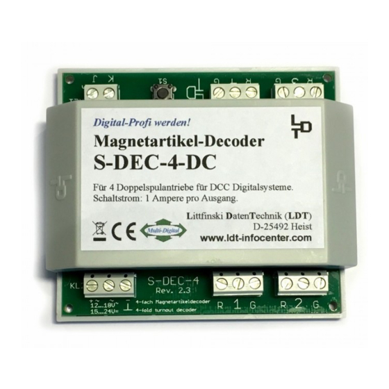
Digital-Profi werden!
Magnetartikel-Decoder
S-DEC-4-DC
Für 4 Doppelspulenantriebe für DCC Digitalsysteme.
Schaltstrom: 1 Ampere pro Ausgang.
Multi-Digital
S-DEC-4
KL2
Rev. 2.3
+ ~
~
-
4-fach Magnetartikeldecoder
12 ... 18V~
15 ... 24V=
4-fold turnout decoder
Now connect turnouts, signals, uncoupling tracks or the
permanent power switch units [DSU] to the 3-pole clamp marked
1 to 4.
The common conductor of a double coil (turnout or semaphore
signal) has always to be connected to the middle clamp of the
relevant decoder output. The two remaining cables mostly
marked with red (turnout round) and green (turnout straight) shall
be connected to the clamps marked ‚R' and ‚G' accordingly.
Programming the decoder addresses:
To program the decoder address a turnout has to be connected
to the output 1 of the decoder.
•
Switch on the power supply of your model rail way.
•
Adjust the speed of all connected speed controller to zero.
•
Press the programming key S1.
•
The turnout connected to output 1 will move now
automatically every 1.5 seconds. This indicates that the
decoder is in the programming mode.
•
Switch now one turnout of the group of four assigned to the
decoder via the keyboard of the control unit or via a remote
control. For programming the decoder address you can also
release a turnout switch signal via a personal computer.
Remarks: The decoder addresses for magnetic accessories
are combined into groups of four. The address 1 to 4 build
the first group. The address 5 to 8 build the second group etc.
Each S-DEC-4-DC decoder can be assigned to any of these
groups. Which turnout of a group will be activated for the
addressing does not matter.
•
If the decoder has recognized the assignment correctly the
connected turnout will move a little faster. Afterwards the
movement slows down to the initial 1.5 seconds again.
Littfinski DatenTechnik (LDT)
www.ldt-infocenter.com
1
2
R
G
R
G
Advertisement
Table of Contents

Subscribe to Our Youtube Channel
Related Manuals for LDT S-DEC-4-DC-G


Summary of Contents for LDT S-DEC-4-DC-G
- Page 1 LDT will also be not liable for any consequential control. For programming the decoder address you can also damages caused by improper use or installation.
- Page 2 Internet: www.ldt-infocenter.com or cross the decoder closely. Install the cables that way that Subject to technical changes and errors. © 05/2019 by LDT they go straight away from the clamps of the decoder. Arnold, Digitrax, Lenz, Märklin, Roco and Zimo are registered trade marks.
Need help?
Do you have a question about the S-DEC-4-DC-G and is the answer not in the manual?
Questions and answers