
Related Manuals for A-Neuvideo ANI-4KANA

Summary of Contents for A-Neuvideo ANI-4KANA
- Page 1 ANI-4KANA 4K UHD+ HDMI Signal Generator & Analyzer AUDIO / VIDEO MANUFACTURER A-NeuVideo.com Frisco, Texas 75036...
- Page 2 SAFETY INFORMATION 1. To ensure the best results from this product, please read this manual and all other documentation before operating your equipment. Retain all documentation for future reference. 2. Follow all instructions printed on unit chassis for proper operation. 3.
- Page 3 NEUVIDEO SAFETY PRECAUTIONS Please read all instructions before attempting to unpack, install or operate this equipment and before connecting the power supply. Please keep the following in mind as you unpack and install this equipment: • Always follow basic safety precautions to reduce the risk of fire, electrical shock and injury to persons. •...
-
Page 4: Table Of Contents
CABLE SPECIFICATIONS.......................96 INTRODUCTION The ANI-4KANA HDMI Signal Generator & Analyzer is an advanced and handy tool for generating, testing and verifying the signal path within your 18Gbps HDMI ecosystem. With (87) built-in resolutions, (56) test patterns and over a dozen types of A/V analysis functions, this unit provides an enormous range of testing options. -
Page 5: Features / System Requirements / Applications
FEATURES / SYSTEM REQUIREMENTS / APPLICATIONS FEATURES • HDMI 2.0 (up to 4K@60Hz 4:4:4) and DVI 1.0 compliant • HDCP 1.4 and 2.2 compliant • Analysis of source and sink data paths up to 18Gbps HDMI signals • Generates HDMI timings up to 18Gbps (4096x2160@60Hz 4:4:4, 8-bit) and VGA timings up to 165MHz (WUXGA, 1920x1200@60Hz RB) •... -
Page 6: Specifications
SPECIFICATIONS • HDMI Bandwidth: 18Gbps • VGA Bandwidth: 165MHz • Input Ports: • HDMI (Type-A) • Stereo Audio (3.5mm) • Output Ports 1xHDMI (Type-A) • VGA (HD-15) • Stereo Audio (3.5mm) • Control Ports: • RS-232 (DE-9) • IP Control (RJ-45) •... -
Page 7: Operation Controls & Functions
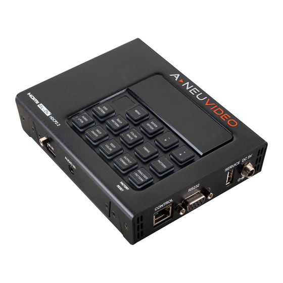
OPERATION CONTROLS & FUNCTIONS TOP PANEL q OLED SCREEN: Displays the current signal analysis information or test pattern mode selection details including input and/or output resolution timing. The screen layout changes depending on the unit’s mode. ANALYZER MODE (Analyzer/Pattern button is RED): Analyzer mode, if there is no live video source detected on the input port, the OLED will display any voltage, TMDS or sync that might be present. - Page 8 OPERATION CONTROLS & FUNCTIONS r ENTER/OPTION: Press to confirm a selection or to go deeper into a menu item. When the selected function has optional selections, the associated button’s LED will illuminate along with the ▼/▲ (-/+) buttons. t +/- & ▲/▼: Press to move up and down or adjust selections within menus.
- Page 9 OPERATION CONTROLS & FUNCTIONS a AUDIO LPCM: Within Analyzer mode, press to select which Serial Data audio source pair (SD0~SD3) is routed to the primary stereo channel (LPCM 2.0 and headphone output) for monitoring. The LED color indicates the selection (Off=SD0, Red=SD1, Blue=SD2, Purple=SD3). Within Pattern mode, press to switch between LPCM 2.0 (LED=Red), 5.1 (LED=Blue) and 7.1 (LED=Purple) channel test tone output formats.
- Page 10 OPERATION CONTROLS & FUNCTIONS SIDE Panels q AUDIO OUT: Connect to powered speakers or an amplifier for stereo analog audio output with a 3.5mm phone jack cable. w VGA OUT PORT: Connect to a VGA (RGBHV) monitor or display for analog video output. NOTE: Only supports RGBHV output (YUV, RGBS, and RGsB are not supported).
-
Page 11: Remote Control
REMOTE CONTROL The IR remote uses one out of (4) available address channels for control of the test pattern generator, allowing up to (4) to be located in the same area while being controlled by different remotes. To configure this, select “IR Controller Address” within the “Setup”... - Page 12 REMOTE CONTROL a MENU: Press to enter the OSD menu. s EXIT: Press to exit the OSD or cancel the selection. d FOR USE IN ANALYZER MODE ONLY: SOURCE: Press to display source signal information on the OSD. VIDEO T: Press to display video analysis details on the OSD.
-
Page 13: Telnet Control
Telnet Control Before attempting to use Telnet control, please ensure that both the unit and the PC are connected to the same active networks. Start your preferred Telnet/Console client, or use the built in client provided by most modern computer operating systems. -
Page 14: Rs-232 Pinout & Defaults / Serial & Telnet Commands
RS-232 Pinout & Defaults / Serial & Telnet Commands RS-232 Protocol SERIAL PORT DEFAULT SETTINGS Baud Rate: 115200bps Data Bits: Parity: None Flow Control: None Stop Bit: Serial & Telnet Commands Before using the commands, please read the following: SYNTAX All commands MUST start with the “$”... - Page 15 Serial & Telnet Commands COMMAND DESCRIPTION $? Show full command list. $HELP Show full command list. Set the number of internally sourced audio output channels. $AUDIO_CH N1 Available values for N1: 2 [2 Channels (2.0)] 6 [6 Channels (5.1)] 8 [8 Channels (7.1)] $AUDIO_CH? ...
- Page 16 Serial & Telnet Commands COMMAND DESCRIPTION $AUDIO_VOL? Show the current audio output volume. Reboot the unit. $BOOT GO NOTE: The unit won’t respond to any commands during the boot process. $BOOT? Show the current boot state. $COLOR_SPACE N1 Set the output color space.
- Page 17 Serial & Telnet Commands COMMAND DESCRIPTION Show the native resolution value stored in the EDID of the selected location. $EDID_NATIVE? N1 Available values for N1: [HDMI Input (Rx) Port] SINK_H [HDMI Sink] SINK_V [VGA Sink] NOTE: First detailed timing from Block 0. If the EDID fails to be read, “$err_ddc”...
- Page 18 Serial & Telnet Commands COMMAND DESCRIPTION Execute a factory reset and reboot the unit. $FACTORY NOTE: Stored Copy EDIDs and Ethernet settings will not be reset. $FWVER? Show the current firmware version. $HDCP_IN_SW N1 Enable or disable HDCP support for the unit’s HDMI input. Available values for N1: [Enable HDCP] OFF [Disable HDCP]...
- Page 19 Serial & Telnet Commands COMMAND DESCRIPTION $HDR_MFALL? Show the current maximum HDR frame-average light level value. Select the current HDR preset group. $HDR_SET N1 N1 = 1~3 [HDR preset group] $HDR_SET? Show the currently selected HDR preset group. Enable or disable HDR support on the unit’s HDMI output.
- Page 20 Serial & Telnet Commands COMMAND DESCRIPTION $NET_STATIC_IP? Show the unit’s static IP address. $NET_STATIC_MASK Set the unit’s static netmask address. N1 N1 = X.X.X.X [X = 0~255, static netmask] $NET_STATIC_MASK? Show the unit’s static netmask address. Select the test pattern to output. $PATTERN N1 ...
- Page 21 Serial & Telnet Commands COMMAND DESCRIPTION HDCP_AKSV [Source HDCP AKSV in 2-digit hex (HDCPv1.4)] $SINK_DETECT? N1 HDCP_BKSV [Rx HDCP BKSV in 2-digit hex (HDCPv1.4)] CONT'D HDCP_RXID [Rx Receiver ID in 2-digit hex (HDCPv2.2)] SCDC [SCDC port status] SCDC_SCR_ENABLE [Rx SCDC source scrambling setting] SCDC_SCR_STATUS [SCDC sink scrambling status] SCDC_SINK_VER...
- Page 22 Serial & Telnet Commands COMMAND DESCRIPTION $SOURCE_DETECT? ASP_LAYOUT [Audio-Sample packet layout] N1 ASP_PLL [Audio-Sample packet PLL (locked or unlocked)] CHS_CODE [Channel-status audio coding] CONT’D CHS_SR [Channel-status sampling rate in KHz] CHS_SS [Channel-status sampling size] CHS_TYPE [Channel-status application type (consumer or professional)] HBR [High-Bit-Rate packet status] AIF [Display packet-AIF data in 2-digit hex]...
- Page 23 Serial & Telnet Commands COMMAND DESCRIPTION Set the unit’s output +5v pin state to follow the TMDS output state or $TX_5V N1 to always be on. Available values for N1: FOLLOW [Only output 5v if there is a live signal.] [Always output 5v.] $TX_5V? ...
- Page 24 OSD Menu All functions of this unit can be controlled by using the OSD (On Screen Display) which is activated by pressing the MENU button on the front of the unit. Use the + (PLUS), − (MINUS), and ENTER buttons to navigate the OSD menu. Press the MENU button to back out from any menu item and then press it again to close the menu.
- Page 25 OSD Menu Analyzer Mode SOURCE MONITOR 2ND LEVEL [Resolution Data] [Signal Data] [Packet Data] [Format Data] 1. Source Monitor: This screen displays a simplified collection of data about the current HDMI source. • Resolution Data: Displays the currently detected resolution and timing information. •...
- Page 26 OSD Menu VIDEO TIMING 2ND LEVEL 3RD LEVEL V Sync Polarity HV Sync Offset 1 [Current Analytical Data] HV Sync Offset 2 Scan Mode 1. Video Timing: These pages display the real-time details of the video source currently connected to the HDMI input. •...
- Page 27 OSD Menu AUDIO TIMING 2ND LEVEL 3RD LEVEL [Current Analytical Data] ACR N ACR CTS -ASP Monitor- FIFO ACR Re-gen [Current Analytical Data] Packet Layout Channel Number Sample Present SD0 Out Swap -ASP Channel Status- App. Type Audio Coding Channel Number [Current Analytical Data] Source Number Sampling Rate...
- Page 28 OSD Menu AUDIO TIMING 2ND LEVEL 3RD LEVEL -ASP LPCM Level- SD3-L [Current Analytical Data] SD3-R 1. Audio Timing: These pages display the real-time details of the audio signal currently detected on the HDMI input. NOTE: Only LPCM sources can be monitored in detail. Bitstream sources will be identified as NLPCM (Not LPCM) and will have reduced information available.
- Page 29 OSD Menu PACKET (Monitor) 2ND LEVEL 3RD LEVEL 4TH LEVEL Monitor 1h ACR 2h ASP 3h GCP 4h ACP 5h ISRC1 6h ISRC2 7h One Bit 8h DST 9h HBR Ah Gamut Bh ASP 3D [Current Analytical Data] Ch One Bit 3D Dh Audio Metadata Eh ASP Multi Fh One Bit Multi...
- Page 30 OSD Menu PACKET (GCP) 2ND LEVEL 3RD LEVEL 4TH LEVEL HB0~HB2 SB0~SB4 [Current Analytical Data] SB5~SB6 AVMUTE Color Depth 1. GCP Packet: This page displays the current details contained within the General Control infoframe Packet. PACKET (AVI) 2ND LEVEL 3RD LEVEL 4TH LEVEL Type Version...
- Page 31 OSD Menu PACKET (AVI) 2ND LEVEL 3RD LEVEL 4TH LEVEL RGB Quant.Range Non-Uniform Scale VIC 97 [Current Analytical Data] YCC Quant.Range IT Contents Type Pixel Repetition 1. AVI Packet: This page displays the current details contained within the Auxiliary Video Information infoframe packet.
- Page 32 OSD Menu PACKET (SPD) 2ND LEVEL 3RD LEVEL 4TH LEVEL Type Version Length Checksum DB 1~DB 5 DB 6~DB10 [Current Analytical Data] DB11~DB15 DB16~DB20 DB21~DB25 Vendor Product Source Information 1. SPDPacket: This page displays the current details contained within the Source Product Description infoframe packet.
- Page 33 OSD Menu PACKET (VSIF H14b) 2ND LEVEL 3RD LEVEL 4TH LEVEL VSIF H14b IEEE ID HDMI Video Format Ext. HDMI VIC [Current Analytical Data] 3D Structure 3D Ext. Data 1. VSIF (HDMI 1.4b) Packet: This page displays the current details contained within the Vendor Specific InfoFrame packet.
- Page 34 OSD Menu PACKET (DRMI (HDR)) 2ND LEVEL 3RD LEVEL 4TH LEVEL DRMI (HDR) white point x white point y max disp mastering lumi min disp mastering lum [Current Analytical Data] Max Content Light-Level Max Frame-average L-L AVI Color Space AVI Colorimetry 1.
- Page 35 OSD Menu EDID ANALYZER 2ND LEVEL 3RD LEVEL 4TH LEVEL HDMI Sink Y420 Video Data Block Y420 Capability Map Video Format Preference [EDID Block 1 Deciphered Speaker & Colorimetry Data] Video Capability Vendor Specific Video DB Detail Timings VGA Sink [Same as HDMI Sink] Rx EDID [Same as HDMI Sink]...
- Page 36 OSD Menu 4. Default & Copied EDID: These pages provide both a raw hex and decoded view of the contents of the first 2 EDID blocks of each internally stored Default or Copied User EDID. • D1~D10: Internal Default EDIDs 1 through 10. •...
- Page 37 OSD Menu 3. Copy VGA Sink EDID to...: Select a Copy EDID numbered slot (C1~C10) to copy and store the EDID from the currently connected VGA display into that slot. The EDID name will be automatically filled in with name data from the copied EDID. NOTE: If a slot already contains EDID data, it will be overwritten by the new EDID.
- Page 38 OSD Menu 1. HDCP Input Monitor (HDCP 1.x): This page displays the real-time details of HDCP 1.4 communication between this unit and the source currently connected to the HDMI input. “Count” lists how many successful key authorizations have occurred and “Day” lists how long the connection has been active and authenticated.
- Page 39 OSD Menu SCDC INPUT MONITOR 2ND LEVEL 3RD LEVEL RR Enable Test Read Request Test Read Delay RR Test Status Update Clock Detected Ch2/1/0 Locked [Current Analytical Data] CED Update Count CED Count Ch0 CED Count Ch1 CED Count Ch2 CED Checksum Timer [ENTER] Reset/Start Counter...
- Page 40 OSD Menu 1. SCDC Input Monitor: These pages display the details of the SCDC (Status and Control Data Channel) of the source currently connected to the HDMI input. The CED (Character Error Detection) data for each of the 3 channels can be monitored in real time. Pressing “Enter” on the CED status page will start live monitoring.
- Page 41 OSD Menu 1. SCDC Input Monitor: 1. Hot Plug Preset: Set the unit’s behavior when the “Hot Plug Run” setting is activated. 2. Hot Plug Toggle Time: Set the length of time for the hot plug to remain low when in toggle mode (in milliseconds).
- Page 42 OSD Menu OUTPUT RESOLUTION Resolution Resolution 640x350p 1280x960p 640x480p 1280x1024p 59.94 1360x768p 720x400p 1366x768p 60 (RB) 800x600p 1400x1050p 60 (RB) 1440x900p 60 (RB) 848x480p 1024x768p 1600x900p 60 (RB) 1600x1200p 1680x1050p 60 (RB) 1152x864p 1280x768p 60 (RB) 1920x1200p 60 (RB) 480i 59.94 480p 59.94...
- Page 43 OSD Menu OUTPUT RESOLUTION Resolution Resolution 3840x2160p 720p 23.976 1080i 59.94 29.97 1080p 23.976 59.94 29.97 4096x2160p 23.976 59.94 29.97 2048x1080p 23.976 59.94 29.97 Auto ►[Native] Bypass 1. Output Resolution: Select a standard scaled resolution (T01~T91) for the source currently being analyzed to be output as, or allow the source to be output completely unmodified by selecting “Bypass”...
-
Page 44: Osd Menu
OSD Menu OSD SETTINGS 2ND LEVEL 3RD LEVEL 0%~100% (10%) H Position 0%~100% (10%) V Position 0~7 (4) Transparency A Mode Color Blue Black P Mode Color BLUE Black Font Type NARROW Wide 1. H/V Position: Set the horizontal and vertical position of the OSD menu. 2. - Page 45 OSD Menu ETHERNET 2ND LEVEL 3RD LEVEL -Link Status- IP Mode IP Address [Current Ethernet Details] Subnet Mask Gateway MAC Address [Unit’s MAC Address] 1. IP Mode: Set the unit to Static or DHCP mode. When DHCP mode is selected, all IP address information will be assigned automatically by the local DHCP server.
- Page 46 OSD Menu SETUP 2ND LEVEL 3RD LEVEL 3D Source Image Bypass Information Refresh 1 Sec 2 SEC Manual IR Controller Address 0~3 (0) OLED Screen Saving Copied EDID Reset Ethernet Reset Factory Reset 1. Firmware Update: Provides a way to update the unit’s firmware via USB. After selecting “Yes”, follow the on-screen prompt and insert a FAT32 formatted USB stick, with a valid firmware file (*.bin format) in the root directory, into the unit’s USB service port.
- Page 47 OSD Menu 4. [Colorbar] with border: Enable or disable a pair of grey border lines around the unit’s color bar patterns (P13~P18). 5. [Letter H] Option 2: Set the font size of the Letter H (P37) pattern’s second display variation. 6.
- Page 48 OSD Menu INFORMATION 2ND LEVEL 3RD LEVEL Packet VIC 16 Color Space/Depth [Current Unit Details] H14b Audio Format Audio PLL FW Ver 1. Information: Displays details about the unit’s current status. To refresh the information on this page, press “Enter”. Pattern Mode SINK MONITOR 2ND LEVEL...
- Page 49 OSD Menu PATTERN Pattern Name Var. Pattern Name Var. Color Magenta Grid Color Red Image Color White Letter H Color Yellow Line On/Off-H Colorbar Delay Line On/Off-V Colorbar-H Line On/Off-V 4K Colorbar Motion Local Dimming COLORBAR S. Motion-H Colorbar Split Motion-V Colorbar-V 3 Multiburst...
- Page 50 OSD Menu AUDIO OUTPUT 2ND LEVEL 3RD LEVEL Source *PoR HDMI In Analog In INT. SINEWAVE 0~80 (70) Volume Analog Out CH SD0 L/R SD1 L/R SD2 L/R SD3 L/R Sampling Rate 48 KHZ 96 kHz 192 kHz Word Length 16 Bits 20 Bits 24 BITS...
- Page 51 OSD Menu AUDIO OUTPUT 2ND LEVEL 3RD LEVEL Source *PoR HDMI In Analog In INT. SINEWAVE 0~80 (70) Volume Analog Out CH SD0 L/R SD1 L/R SD2 L/R SD3 L/R Sampling Rate 48 KHZ 96 kHz 192 kHz Word Length 16 Bits 20 Bits 24 BITS...
- Page 52 OSD Menu 5. Word Length: Set the internal sine wave test tone word length. 6. Channels: Set the number of LPCM audio channels to have active when outputting the internal sine wave test tone. 7. SD0-L~SD03-L Freq: Set the internal sine wave test tone frequency, in 200Hz steps, for each distinct “left”...
- Page 53 OSD Menu EDID ANALYZER 2ND LEVEL 3RD LEVEL 4TH LEVEL HDMI Sink Y420 Capability Map Video Format Preference cont’d Speaker & Colorimetry [EDID Block 1 Deciphered Data] Video Capability Vendor Specific Video DB Detail Timings VGA Sink [Same as HDMI Sink] Rx EDID [Same as HDMI Sink] Default &...
- Page 54 OSD Menu 4. Default & Copied EDID: These pages provide both a raw hex and decoded view of the contents of the first 2 EDID blocks of each internally stored Default or Copied User EDID. • D1~D10: Internal Default EDIDs 1 through 10. •...
- Page 55 OSD Menu 2. Copy HDMI Sink EDID to...: Select a Copy EDID numbered slot (C1~C10) to copy and store the EDID from the currently connected HDMI display into that slot. The EDID name will be automatically filled in with name data from the copied EDID. NOTE: If a slot already contains EDID data, it will be overwritten by the new EDID.
- Page 56 OSD Menu HDCP OUTPUT MONITOR (HDCP v1.4 Output) 2ND LEVEL 3RD LEVEL -Repeater- Authentication Cascade Depth [Current Analytical Data] Downstream Device -Link Integrity- Ri Tx Ri’ Sink [Current Analytical Data] Count 1. Monitor HDCP (HDCP 1.4 Output): These pages display the realtime details of HDCP 1.4 communication between this unit and the device currently connected to the HDMI output.
- Page 57 OSD Menu HDCP OUTPUT MONITOR (HDCP v2.2 Output) 2ND LEVEL 3RD LEVEL Ekpub_km AKE_No_Stored_km() AKE_Send_H_prime() Compare H/H’ AKE_Send_Pairing_Info() Ekh_km() [Current Analytical Data] LC_Init() LC_Send_L_prime() Compare L/L’ Edkey_ks SKE_Send_Eks() -Repeater- Authentication Cascade Depth [Current Analytical Data] Downstream Device Content Type -Link Integrity- RxStatus.REAUTH_RQ Count [Current Analytical Data]...
- Page 58 OSD Menu HDR OUTPUT EMULATOR 2ND LEVEL 3RD LEVEL HDR Out On/Off 1~3 (1) Settings Value Unit NIT (CD/M*M) Tx AVI Colorimetry No Data ITU601 ITU709 xvYCC601 xvYCC709 sYCC601 Adobe Y601 Adobe RGB BT.2020 (1) BT.2020 (2) EOTF 0: SDR Luminance Range 1: HDR Luminance Range 2: SMPTE ST 2084[2] 3: Future EOTF...
- Page 59 OSD Menu HDR OUTPUT EMULATOR 2ND LEVEL 3RD LEVEL 0~65500 (0) Max Frame-average L-L Tx AVI Color Space [Current Analytical Data] Sink EDID supports HDR 1. HDR Out On/Off: Enable or disable the HDR output simulation mode. NOTE: Enabling HDR will change the HDMI output’s AVI and DRMI packets to indicate an HDR signal to the connected display and activate the connected display’s HDR mode, however all test patterns generated by this unit will continue to be 8-bit color within the SDR color range.
- Page 60 OSD Menu 15. Tx AVI Color Space: Shows the currently active output color space. 16. Sink EDID supports HDR: Display the reported HDR capability of the connected display. SCDC OUTPUT MONITOR 2ND LEVEL 3RD LEVEL Sink Version Source Version Scrambling Enable TMDS Bit Clock Ratio Scrambling Status RR Enable...
- Page 61 OSD Menu 15. Tx AVI Color Space: Shows the currently active output color space. 16. Sink EDID supports HDR: Display the reported HDR capability of the connected display. SCDC OUTPUT MONITOR 2ND LEVEL 3RD LEVEL OUI3/2/1 Device ID H/W Major Rev. [Current Analytical Data] H/W Minor Rev.
- Page 62 OSD Menu TX PORT CONTROLS 2ND LEVEL 3RD LEVEL HDCP Output On/Off *PoR HDCP Output Version V1.4 v2.2 HDCP Counter Reset HDCP2 AKE_Stored_km() HDCP2 Rep. Content Type 0~1 (0) SCDC CED Counter Read SCDC CED Always Read SCDC CED Ch Auto Clear 1.
- Page 63 OSD Menu 7. SCDC CED Counter Read: When enabled, the unit will read the sink’s Ch0~2 Error Counter. 8. SCDC CED Always Read: When enabled, the unit will ignore the sink’s CED_Update flag. 9. SCDC CED Ch Auto Clear: When disabled, this setting allows the unit to accumulate CED values while monitoring, rather than the value being automatically cleared.
- Page 64 OSD Menu OUTPUT RESOLUTION Resolution Resolution 2048x1080p 1680x1050p 1920x1200p 60 (RB) 29.97 480i 59.94 480p 59.94 3840x2160p 576i 23.976 576p 720p 59.94 29.97 720p 1080i 59.94 59.94 1080p 4096x2160p 23.976 23.976 29.97 29.97 59.94 59.94 2048x1080p 23.976 Auto ►[Native] 1. Output Resolution: Select an output resolution (T01~T91) for the currently selected test pattern.
- Page 65 OSD Menu OSD SETTINGS 2ND LEVEL 3RD LEVEL 0%~100% (10%) H Position 0%~100% (10%) V Position 0~7 (4) Transparency A Mode Color Blue Black P Mode Color BLUE Black Font Type NARROW Wide 1. H/V Position: Set the horizontal and vertical position of the OSD menu. 2.
- Page 66 OSD Menu ETHERNET 2ND LEVEL 3RD LEVEL -Link Status- IP Mode IP Address [Current Ethernet Details] Subnet Mask Gateway MAC Address [Unit’s MAC Address] 1. IP Mode: Set the unit to Static or DHCP mode. When DHCP mode is selected, all IP address information will be assigned automatically by the local DHCP server.
- Page 67 OSD Menu SETUP 2ND LEVEL 3RD LEVEL 3D Source Image Bypass Information Refresh 1 Sec 2 SEC Manual IR Controller Address 0~3 (0) OLED Screen Saving Copied EDID Reset Ethernet Reset Factory Reset 1. Firmware Update: Provides a way to update the unit’s firmware via USB. After selecting “Yes”, follow the on-screen prompt and insert a FAT32 formatted USB stick, with a valid firmware file (*.bin format) in the root directory, into the unit’s USB service port.
- Page 68 OSD Menu 4. [Colorbar] with border: Enable or disable a pair of grey border lines around the unit’s color bar patterns (P13~P18). 5. [Letter H] Option 2: Set the font size of the Letter H (P37) pattern’s second display variation. 6.
- Page 69 OSD Menu INFORMATION 2ND LEVEL 3RD LEVEL -Tx- Color Space/Depth Audio Source [Current Output Details] Audio Format FW Ver [Current Firmware] [ENTER] Refresh 1. Information: Displays details about the unit’s current output status and detected details from the connected display. To refresh the information on this page, press “Enter”.
-
Page 70: Test Patterns
Test PATTERNS 1. BORDER The Border pattern presents 4 equal-sized squares dividing the screen into 4 quadrants, forming a central white cross, with red, green, blue and white inner squares. Ideal for testing screen boundary, alignment and pincushion issues. All lines should be straight, and edge transitions should be sharp. - Page 71 Test PATTERNS 13. COLORBAR DELAY The Colorbar Delay pattern provides a sequence of standard 100% color bars with a full set of smaller color squares within each bar. This test is primarily to detect if any of the color components of the video signal are delayed/skewed relative to each other.
- Page 72 Test PATTERNS 19. CROSS HATCH 8 VARIATION 1 VARIATION 2 Normal Inverse The Cross Hatch 8 pattern is a full field black & white pattern of crossing vertical and horizontal lines dividing the screen into (8) sections in each direction. This pattern is primarily used to check for color convergence and pincushion issues in projectors.
- Page 73 Test PATTERNS 24. DOT The Dot pattern is a full field black & white pattern with a repeating pattern of single-pixel (resolutions below 4K) or 4-pixel (at 4K) white dots surrounded by single pixels of black. This pattern is ideal for testing the signal path/display for bandwidth issues, interference, cross-talk or scaling issues.
- Page 74 Test PATTERNS 28. GRAYSCALE 16 VARIATION 1 VARIATION 2 VARIATION 3 Vert. Bar Vert. L/R Bar Hori. Bar The Grayscale 16 pattern provides a way to check and adjust the contrast, brightness and grayscale tracking of your display with (16) bars progressing from 0% to 100% brightness in even steps.
- Page 75 Test PATTERNS The Grayscale 256 pattern provides a way to fine tune the contrast, brightness and grayscale tracking of your display with a full (265) step gradient progressing from 0% to 100% brightness. When testing a display, no color should be visible at any point across the gradient, and the transition from black to white should appear even and consistent.
- Page 76 Test PATTERNS 37. LETTER H VARIATION 1 VARIATION 2 Large H Small H The Letter H pattern is a screen filled with a series of large capital “H” characters moving vertically up the screen. This is a basic test to confirm motion detail. There are (2) variations: Large “H” characters and small “H”...
- Page 77 Test PATTERNS 41. LOCAL DIMMING VARIATION 1 VARIATION 2 White Line White Square The Local Diming pattern generates either a white line, or white square that moves slowly across a black screen to test the behavior and quality of a display’s local dimming function. The white line variation moves left to right, then top to bottom while the white square variation moves clockwise around the outer edge of the display, then diagonally, from corner to corner.
- Page 78 Test PATTERNS 41. LOCAL DIMMING VARIATION 1 VARIATION 2 VARIATION 3 No Motion Slow Motion Fast Motion The Multiburst pattern provides a standard multiburst pattern consisting of vertical white lines that decrease in thickness from left to right allowing the user to analyze the bandwidth and frequency response of the video path and connected display.
- Page 79 Test PATTERNS 49. SQUARE H8 VARIATION 1 VARIATION 2 Normal Inverse The Square H8 pattern is a full field black & white pattern of squares dividing the screen horizontally into 8 sections. This pattern is primarily used to check projector linearity. There are 2 variations: Normal (white lines, black field) and Inverse (black lines, white field).
- Page 80 Test PATTERNS 53. WINDOW BLUE VARIATION 1 VARIATION 2 VARIATION 3 VARIATION 4 Normal 75% Inverse 75% Normal 50% Inverse 50% 54. WINDOW CYAN VARIATION 1 VARIATION 2 VARIATION 3 VARIATION 4 Normal 75% Inverse 75% Normal 50% Inverse 50% 55.
- Page 81 Test PATTERNS 59. WINDOW YELLOW VARIATION 1 VARIATION 2 VARIATION 3 VARIATION 4 Inverse 75% Normal 50% Normal 75% Inverse 50% These Window patterns are additional screen purity tests offering seven different patterns with different sized windows of each color on a black field: Blue, Cyan, Green, Magenta, Red, White, Yellow.
-
Page 82: Connection Diagram
CONNECTION DIAGRAM... -
Page 83: Anapat Software
Start menu and it will have the same icon as seen here. CONNECTION The Anapat software can connect to the ANI-4KANA via RS-232 or Ethernet. The ANI-4KANAL via RS-232 (Using the Micro-USB port). Please follow the steps below to connect using the method appropriate for the device you wish to control. - Page 84 anapat SOFTW ARE Step 4: Double click on the IP address of the unit you want to connect to or manually type it into the space provided. Step 5: If the connection button is showing Red ( ), click it to initiate the connection. The “Not Linked”...
- Page 85 anapat SOFTW ARE SOFTW ARE OPERATION All major functions of the Signal Generator & Analyzer units are accessible from the tabs and buttons provided in the main window of the Anapat software. These include operation mode selection, EDID management, output resolution selection, pattern selection, function control, sink/source monitoring, and cable testing (ANI-4KANAL only).
- Page 86 This tab provides control over the unit’s EDID Management including options to select, read, write, analyze and save any EDID available to the unit. These functions are primarily used when in Analyzer Mode, however they are available in both modes. Figure 3: EDID Management in Analyzer Mode, ANI-4KANA...
- Page 87 SOFTW ARE Figure 4: Rx EDID Selection in Analyzer Mode, ANI-4KANA q RENAME: Renames the currently selected “Write to:” EDID to the text typed into the entry box. w PRE-F: Opens a quick-access list of recently opened EDID files.
- Page 88 These functions are available for both Analyzer Mode and Pattern Mode. NOTE: The “Bypass” output resolution only works in Analyzer mode. The image below is from the ANI-4KANA of the unit. The list of available resolutions for the ANI-4KANAL is more limited. Figure 5: Output Resolution in Pattern Mode, ANI-4KANA The output resolution that is currently in use is displayed near the top of the window.
- Page 89 This tab provides control over the unit’s test patterns and allows setting “Favorite Patterns” for quick selection. This function is only available in Pattern Mode. NOTE: The image below is from the ANI-4KANA of the unit. The list of available patterns for the ANI-4KANAL is more limited.
- Page 90 The available controls change depending on the unit’s current operational mode (Analyzer or Pattern), and which functions are appropriate based on the unit’s current output resolution and pattern selection. Figure 8: Control Panel in Analyzer Mode, ANI-4KANA Figure 9: Control Panel in Pattern Mode, ANI-4KANA...
- Page 91 This tab provides access to a full suite of real-time monitoring and analysis functions covering a wide range of data from both the input and output. Figure 10: Monitoring in Analyzer Mode, ANI-4KANA Figure 11: Monitoring in Pattern Mode, ANI-4KANA...
- Page 92 anapat SOFTW ARE The available Real-time Monitor categories are: q SYSTEM: Basic source, sink and unit signal information. w VIDEO TIMING (ANALYZER MODE ONLY): Detailed information about the source’s video timing. e AUDIO TIMING (ANALYZER MODE ONLY): Detailed information about the source’s audio format. r PACKET (ANALYZER MODE ONLY): Detailed information about the source’s GCP, AVI, AIF, SPD, VSI, and DRMI packets.
- Page 93 anapat SOFTW ARE Step 3: Click on the “Start” button and wait for the test process bar to complete. A test in “Normal” mode usually takes about two minutes to complete. Step 4: The software will display the result of the testing (PASS or FAIL). More detailed information from the test is available on the unit itself.
-
Page 94: Video Specifications
Video Specifications Standard Resolution Support Input Output Output (Bypass) (Pattern) HDMI HDMI HDMI Supported Resolutions (Hz) 720x400p@70/85 ü ü ü 640x480p@60/72/75/85 ü ü ü 720x480i@60 ü ü 720x480p@60 ü ü ü 720x576i@50 ü ü 720x576p@50 ü ü ü 800x600p@56/60/72/75/85 ü ü... - Page 95 Video Specifications Standard Resolution Support Input Output Output (Bypass) (Pattern) Supported Resolutions (Hz) HDMI HDMI HDMI 3840x2160p@50/60 ü ü 4096x2160p@24/25/30 ü ü 4096x2160p@50/60 (4:2:0) ü ü 4096x2160p@24, HDR10 ü ü 4096x2160p@50/60 (4:2:0), HDR10 ü ü 4096x2160p@50/60 ü ü Supported Color Formats YCbCr YCbCr YCbCr...
- Page 96 Video Specifications Source Video Timing Index Source Video Timing Index Resolution Resolution 640x350p 1280x800p 640x480p 1280x960p 59.94 1280x1024p 720x400p 1360x768p 800x600p 1366x768p 60 (RB) 1400x1050p 60 (RB) 1440x900p 848x480p 60 (RB) 1024x768p 1600x900p 60 (RB) 1152x864p 1600x1200p 1680x1050p 60 (RB) 1280x768p 60 (RB) 1920x1200p...
- Page 97 Video Specifications Source Video Timing Index Resolution Resolution 720p 2048x1080p 29.97 29.97 59.94 59.94 3840x2160p 29.97 23.976 59.94 29.97 1080i 59.94 59.94 1080p 4096x2160p 23.976 23.976 29.97 29.97 1080p 59.94 59.94 2048x1080p 23.976 Not Supported...
-
Page 98: Audio Specifications
Audio Specifications Digital Audio HDMI Input / Output (Bypass) LPCM Max Channels 8 Channels Sampling Rate (kHz) 32, 44.1, 48, 88.2, 96, 176.4, 192 Bitstream Supported Formats Standard & High-Definition HDMI Output (Test Tone Generation) LPCM Max Channels 8 Channels 48, 96, 192 Sampling Rate (kHz) Note: 192kHz only supports 2 channels... -
Page 99: Cable Specifications
Cable Specifications 1080p 4K30 4K60 (4:4:4) (4:4:4) Cable Length 8-bit 12-bit 8-bit 8-bit High Speed HDMI Cable HDMI Input 49ft/15M 32ft/10M 16ft/5M 9ft/3m HDMI Output 49ft/15M 32ft/10M 16ft/5M 9ft/3m Bandwidth Category Examples: • 1080p (FHD Video) • Up to 1080p@60Hz, 12-bit color •... - Page 100 THROUGH OR UNDER A-NeuVideo, INC (COLLECTIVELY, THE “PRODUCT”). By using installing or using the Product, you unconditionally signify your agreement to these Terms and Conditions. If you do not agree to these Terms and Conditions, do not use the Product and return the Product to A-NeuVideo, Inc. at the return address set forth on the Product’s packing label at your expense.
Need help?
Do you have a question about the ANI-4KANA and is the answer not in the manual?
Questions and answers