Table of Contents
Advertisement
Quick Links
HL-25H OPERATION MANUAL
HESHBON CO., LTD.
673-52, Gyeongseo-dong, Seo-gu Incheon 404-170, KOREA
Copyright HESHBON CO., LTD. ⓒ 2002
First Printing, February 2002
HESHBON CO., LTD. developed this document for its licensees and customers. The information
contained herein is the property of HESHBON CO., LTD. and may not be copied, used, or
disclosed to others without prior written approval from HESHBON CO., LTD.. Users are
cautioned that the material contained herein is subject to change by HESHBON CO., LTD. at any
time and without prior notice
LIFT
English Version
HBN-H-301-09/VER. 2.0
Printed in Korea
Advertisement
Table of Contents

Related Manuals for HESHBON HL-25H


Summary of Contents for HESHBON HL-25H
- Page 1 HESHBON CO., LTD. developed this document for its licensees and customers. The information contained herein is the property of HESHBON CO., LTD. and may not be copied, used, or disclosed to others without prior written approval from HESHBON CO., LTD.. Users are cautioned that the material contained herein is subject to change by HESHBON CO., LTD.
- Page 2 : Car Lift Type : HL-2500E, HL-26K, HL-31X, HL-3000N, HL-41G, HL-51G HL-25H , HL-26P, HL-31S , HL-32S, HL-32F , HL-3300J , 3300W, HL-46H Serial Number: (name, type or model, lot, batch or serial number, possibly sources and numbers of items) to which this declaration relates is in conformity with the following standard(s) or other normative document(s);...
- Page 3 HBN-H-301-09/VER. 2.0 Document Revision Guide Document Revision Guide Pages Version Date Changes affected 2/2002 Initial Release 1/2009 Modify Content...
- Page 4 Please read this instruction carefully for safe and proper use of the car lift, and keep it handy for future reference. This Manual is for model ; HL-25H 1. AS FOR THE ASSURANCE OF SAFETY IN DESIGN AND CONSTRUCTION OF CAR LIFT, READ THIS MANUAL FIRST.
- Page 5 - Movement or transfer without contractor's consent; - Consumable items in normal operating; - Any other carelessness not attributable to contractor. Contact your sales agent for warranty coverage. HESHBON CO., LTD. 673-52, Gyeongseo-dong, Seo-gu Incheon 404-170, KOREA Tel ) INT +82-32-585-3570 FAX ) INT +82-32-585-3485...
-
Page 6: Table Of Contents
HBN-H-301-09/VER. 2.0 TABLE OF CONTENTS - TABLE OF CONTENTS COVER SHEET Declaration of Conformity Document Revision Guide NOTE TO THE USER WARRANTY Table of Contents CHAPTER 1. SAFEGUARDS 1-1 Important Notices ............... 1-1 1-2 Qualified Personnel ............. 1-2 1-3 Danger Notices ..............1-3 1-4 Principle safety objective............ - Page 7 HBN-H-301-09/VER. 2.0 CHAPTER 5. TROUBLESHOOTING 5-1 Inspection and repair ............5-1 CHAPTER 6. MAINTENANCE 6-1 General caution during maintenance ........6-1 6-2 Check List and periodic maintenance ........6-1 6-3 Lubricant ................6-3 APPENDIX 1. ELECTRIC DRAWING 2. RECOMMENDED SPARE PARTS LIST...
-
Page 8: Chapter 1. Safeguards
CE mark, declaring conformity with all relevant EN standards in respect of safety systems and car lift construction. All HESHBON MACHINERY carry the CE mark and thus conform with the EU Directives. Any modification to the car lift may invalidate the original CE certificate, and therefore always refer to HESHBON MACHINERY as reassessment may be required. -
Page 9: Qualified Personnel
The purchase agreement contains the complete and exclusive obligations of HESHBON Co., Ltd. Any statements contained in this document do not create new warranties or restrict the existing warranty. -
Page 10: Danger Notices
HBN-H-301-09/VER. 2.0 SAFEGUARDS Qualified persons as referred to in the safety precautions in this document as well as on the car lift itself are defined as follows; ● Operating personnel who have been trained work with the car lift and are conversant with the contents of the documents in as far as it is connected with the actual operation of the car lift;... -
Page 11: Principle Safety Objective
HBN-H-301-09/VER. 2.0 SAFEGUARDS 1-4 Principle safety objective 1) The principle safety objective is to remove the possibility of any hazard or risk to the health or safety of the car lift's operator or service personnel. 2) Extreme caution must be exercised while servicing or installing the car lift. -
Page 12: Safety Notices
HBN-H-301-09/VER. 2.0 SAFEGUARDS 1-5 Safety notices To protect the operator or service personnel from any injuries or accidents during operating the car lift, please read this section and carefully for safe and proper use of the car lift. ◈ General Safeguards 1.Please read carefully this instruction manual for safe and proper use of the car lift. - Page 13 HBN-H-301-09/VER. 2.0 ◈ Caution Notice CAUTION Only qualified personnel should be allowed to work on this car lift. Unexpected accidents may be happened due to wrong operation. Do not lower the lift in the state of supporting a car by a stick to attach or detach components. The car may fall down.
- Page 14 HBN-H-301-09/VER. 2.0 SAFEGUARDS CAUTION Use the lift after reading carefully the instruction manual and understand the contents of them for safe and proper use of the car lift. If a user does not follow a warnings, a serious accident may be happened. When the car enter into the lift, keep the balance of before and behind, and right and left of the car.
- Page 15 HBN-H-301-09/VER. 2.0 SAFEGUARDS WARNING < During lifting and lowering the lift > 5. During moving up or down the lift, you should always watch the car without looking at something else. 6. If several lift are installed, the respective allocation of the switch shall be clear.
- Page 16 HBN-H-301-09/VER. 2.0 SAFEGUARDS WARNING < During repairing the car > 19.Check if the safety lock device is properly operated before operation. 20.Prohibit the unauthorized persons from accessing to the lift. 21.When the operator is not in the lift for a long time, or the lift is not operating, lower completely the lift.
-
Page 17: Essential Safety Checks (Esc's)
HBN-H-301-09/VER. 2.0 SAFEGUARDS 1-6 Essential Safety Checks (ESC's) The essential safety checks are the most important part of the operators responsibility. The purpose of the ESC's is to ensure the safety features of the car lift are functioning properly, and thus the car lift is in a safe condition for use. In addition to the operator it is recommended that regular additional ESC's are carried out by the responsible person and that a record is maintained in accordance with the EU machinery Regulations. -
Page 18: Safety Signs And Warnings Location
HBN-H-301-09/VER. 2.0 SAFEGUARDS 1-7 Safety Signs and Warnings location 1-11... - Page 19 HBN-H-301-09/VER. 2.0 SAFEGUARDS Warning Label 1-12...
-
Page 20: Illumination
HBN-H-301-09/VER. 2.0 SAFEGUARDS 1-8 Illumination This machine is not provided with a local lighting since it is designed for indoor use only. The sufficient illumination of the working area must be fulfilled by the factory in accordance with the appropriate code of practice and factory regulations. -
Page 21: Chapter 2. Overview Of Machine
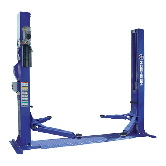
OVERVIEW OF MACHINE CHAPTER 2. OVERVIEW OF MACHINE HL-25H is the stationary two column lift with a rated capacity 4.0 ton which are designed to raise vehicles totally, for the purpose of examing and working on or Under the vehicles whilst in a raised position, 2-1 Specification Model No. -
Page 22: Description Of Construction
HBN-H-301-09/VER. 2.0 OVERVIEW OF MACHINE 2-2 Description of Construction 2-2-1 Assembly PARTS LIST PARTS LIST DRIVE POST LONG ARM DRIVEN POST SHORT ARM CARRY POWER UNIT UPPER SUPPORT BEAM CONTROL PANEL CYLINDER... - Page 23 HBN-H-301-09/VER. 2.0 OVERVIEW OF MACHINE 2-2-2 Construction of post PARTS LIST PARTS LIST PARTS LIST POST LOCKER SPRING 2 LOCK WIRE UPPER ROLLER SNAP RING LEVER SHAFT UP LIMIT SWITCH LOCKER COVER LEVER HANDLE LIMIT S/W BRACKET LOCKER BLOCK LOCKER SPACER LEVEL WIRE ROLLER PIN LEVER CONNECTOR LOCK WIRE ROLLER...
- Page 24 HBN-H-301-09/VER. 2.0 OVERVIEW OF MACHINE 2-2-3 Construction of Arm and Carry PARTS LIST PARTS LIST CARRIER ARM PIN CARRY GUIDE LONG ARM BODY CHAIN ROLLER ARM SUPPORT RUBBER CHAIN ROLLER PIN ARM SUPPORTER CHAIN ROLLER BRACKET ARM 2 SUPPORTER CYLINDER MOUNT LONG ARM SLIDER CYLINDER GUIDE SHORT ARM BODY...
- Page 25 HBN-H-301-09/VER. 2.0 OVERVIEW OF MACHINE 2-2-4 Construction of Base PARTS LIST BASE BODY BASE COVER LEVEL WIRE PROTECT GUIDE...
- Page 26 HBN-H-301-09/VER. 2.0 OVERVIEW OF MACHINE 2-2-5 Construction of Hydraulic PARTS LIST MOTOR OIL PRESSURE BLOCK CHECK VALVE OIL PUMP OIL TANK STRAINER RETURN PIPE STICKING BLACKET VIBRATION PROTECTED RUBBER...
- Page 27 HBN-H-301-09/VER. 2.0 OVERVIEW OF MACHINE Hydraulic circuit 2-2-6...
- Page 28 HBN-H-301-09/VER. 2.0 OVERVIEW OF MACHINE Pneumatic Circuit 2-2-7...
-
Page 29: Flowchart For Operation
HBN-H-301-09/VER. 2.0 OVERVIEW OF MACHINE 2-3 Flowchart for operation The lifting, lowering or stopping of lift is carried out by pressing the switch on the control box. The followings are the flowchart for operation. -
Page 30: Safety Device
HBN-H-301-09/VER. 2.0 OVERVIEW OF MACHINE 2-4 Safety device The following safety devices ares installed at this lift. Device Description Safety Lock The safety lock is attached to the side of cylinder and protects the lowering of lift when an hydraulic oil is leaked or hydraulic circuit is damaged. -
Page 31: Chapter 3. Transportation And Installation
CHAPTER 3. TRANSPORTATION AND INSTALLATION This chapter explains how to install your lift. Always read it ahead of time, even when the lift is installed by HESHBON Co., Ltd. or the place of purchase. Please refer to this chapter when you re-locate your lift. -
Page 32: Precaution During Installation
INSTALLATION OF MACHINE HBN-H-301-09/VER. 2.0 3) The distance between the ceiling and the highest point of load while MIN 200mm lifting to the upper limit should be maintained more than 200mm 3-2 Precaution during installation 1) Maintain the lift about 1m or more away from the wall in order to ensure the sufficient work space. -
Page 33: Transportation
Check all accessories and spares against the provided packing list. When you ordered optional equipment, check the equipment against the accessories and spares against packing list. Contact HESHBON CO., LTD. immediately if any parts is missing or damaged. -
Page 34: Installation
HBN-H-301-09/VER. 2.0 INSTALLATION OF MACHINE 3-4 Installation The installation should be carried out in accordance with the following procedures. 1. After checking the parts, arrange them to the installation site as follows; 2. Install the Base. 1) Level the location to be installed. 2) Because the location of Base corresponds to the position examine and working on or under the vehicles, determine the location to be installed as below figure ;... - Page 35 HBN-H-301-09/VER. 2.0 INSTALLATION OF MACHINE leve 3.Adjust the levelity of the Base with the seam plate using a leveller. After completing the adjustment of levelity, fasten tightly the anchor bolt. 4. Erect a post. 1) The driven post shall be positioned to the left side and the drive post os shall be locations to the right side form the entering direction of vehicle.
- Page 36 INSTALLATION OF MACHINE HBN-H-301-09/VER. 2.0 5. Hold up both carry with the hands and then, hook both carry at the first locker. 6. Fasten the fixing bolt at post base using spanner. When fastening the fixing bolt, the upper side of post Shall 20mm outside from the lower post.
- Page 37 HBN-H-301-09/VER. 2.0 INSTALLATION OF MACHINE 9. Connect the wire rope in the below sequences and then,fix the rope at the carry. Right and left carry ⇒ Lower sheave ⇒ Base ⇒Opposite lower sheave ⇒ Upper sheave ⇒ Bottom ⇒ Fixing the rope at the carry 10.
- Page 38 HBN-H-301-09/VER. 2.0 INSTALLATION OF MACHINE 13. Moving up and down the car lift, listen to the locking sound and then. fasten them. 1) Move up the nut located at the direction with the late sound and then, fasten them. 2) After confirming the levelity of carrier, fasten securely the fixing bolt at end piece of wire rope to the carry.
- Page 39 HBN-H-301-09/VER. 2.0 INSTALLATION OF MACHINE 17. Put on the base cover and then, fasten the bolts at the 4 holes of cover. 18. Supply the power to turn on the CAM switch and check if the power lamp is lighten ON. 19.
- Page 40 HBN-H-301-09/VER. 2.0 INSTALLATION OF MACHINE 22. If the above no-load test run passes satisfactorily, you can make test run under load. It is convenient to record the test result for future maintenance. Check items Result ① Check if the oil at the hydraulic line and nipple is leaked.
-
Page 41: Chapter 4. Operation
OPERATION HBN-H-301-09/VER. 2.0 CHAPTER 4. OPERATION 4-1 Warning for use Only qualified personnel should be allowed to work on this car lift. WARNING 4-2 Checking point before operation ● Check the below items every day before operation. During checking, do not load a car on the lift. ●... -
Page 42: Preparation Before Operation
HBN-H-301-09/VER. 2.0 OPERATION 4-3 Preparation before operation Check the following items before loading a car into the lift; (1) Lower completely the lift to the bottom. (2) Prohibit the unauthorized persons from accessing to the lift. (3) When use the lift which has not operated for a long time, check the oil conditions and functions of each part and then, use the lift after lifting and lowering to press the UP and DOWN switch 2 or 3 times at the... -
Page 43: Operation
HBN-H-301-09/VER. 2.0 OPERATION 4-4-2 Description of control panel Switch and Lamp Function description CAM switch for supplying the power at the car lift. Before the machine is operated, this switch should be turned ON. And also, this switch may use to turn off the power when the emergency situation is occured at the machine. - Page 44 HBN-H-301-09/VER. 2.0 OPERATION 4-5 Operation The procedure for operating the lift is as follows; 1. Lower the carry to the ground by moving down the manual lever for lowering the lift. 2. Spread the arm at its maximum so that the car can be entered into the lift.
-
Page 45: How To Lower Manually The Lift During Emergency
OPERATION HBN-H-301-09/VER. 2.0 4-6 How to lower manually the lift during emergency 4-6-1 When the manual operation is needed. When you can not be carried out the manual operation, contact our company for A/S. CAUTION 1) When the power supplied at lift is interrupted and hydraulic circuit is damaged. - Page 46 HBN-H-301-09/VER. 2.0 OPERATION 4-6-3 Operation procedures 1) Open the cover for protecting the locker with + driver. 2) Release the locker with the fine wire. ( When the locker is not released, release the locker after moving up more than 30mm the carry using hydraulic jack.
-
Page 47: Chapter 5. Troubleshooting
HBN-H-301-09/VER. 2.0 TROUBLESHOOTING CHAPTER 5. TROUBLESHOOTING 5-1 Inspection and repair Symptoms Check point Corrective Action to be taken Platform is not leveled 1. Adjust the fixing bolt of wire rope after checking 1. Check if wire rope is partially loosened. when lift is moving up the levelity. -
Page 48: Chapter 6. Maintenance
HBN-H-301-09/VER. 2.0 MAINTENANCE CHAPTER 6. MAINTENANCE 6-1 General caution during maintenance 1) Maintenance should be performed by more than two persons. 2) Maintenance should be carried out after putting a sign-board of "NO ENTRANCE" at work area. 3) Don't disassemble the system before you are familar with the disassembling sequence. -
Page 49: Check List And Periodic Maintenance
HBN-H-301-09/VER. 2.0 MAINTENANCE 6-2 Check List and periodic maintenance Inspection Items to be Inspection Action to be Points to be checked period checked method taken Rubber Support for Abrasion and deformation Visual Replacement adjustment 1 week Magnetic contactor Damage of contact Measurement Replacement Abrasion, deformation Wire Rope... -
Page 50: Lubricant
HBN-H-301-09/VER. 2.0 MAINTENANCE 6-3 Lubricant The supply of oil or grease on the nipple or friction parts will reduce the loss of power consumption from the friction and minimizes its loss and it increase the efficiency of the machine. The followings are the oil supplying plan. Oil supplying plan Location to be applied Kinds of oil or grease... -
Page 51: Appendix
APPENDIX 1. ELECTRIC DRAWING 2. RECOMMENDED SPARE PARTS LIST... - Page 52 APPENDIX 1.ELECTRIC CIRCUIT –25H (AC 220 15A)
- Page 53 2. ELECTRIC CIRCUIT –25H (AC 380 10A)
- Page 54 Solenoid SV-121 DC 24V PNEUMATICS CORP Bridge Diode KBPC 10A 50V KOREA AUTO Limit Switch M-904 CONTROL or HAN YOUNG ZCN P-501A HL-25H Micro Switch HAN YOUNG 10A 250V HL-26P Push Button KOREA AUTO KD5BRRER10S Switch CONTROL Pilot Lamp DC24...
Need help?
Do you have a question about the HL-25H and is the answer not in the manual?
Questions and answers
Hey both locks are out but it still wont lower
The HESHBON HL-25H lift may not lower even though both locks are out due to a malfunction in the check valve, which maintains hydraulic pressure to prevent unintended lowering. Additionally, issues with the manually lowering valve, hydraulic oil leaks, or electrical faults could also be preventing proper operation. Performing a troubleshooting check on these components can help identify the issue.
This answer is automatically generated