Table of Contents
Advertisement
Quick Links
Advertisement
Table of Contents

Related Manuals for mru MGAprime Q


Summary of Contents for mru MGAprime Q
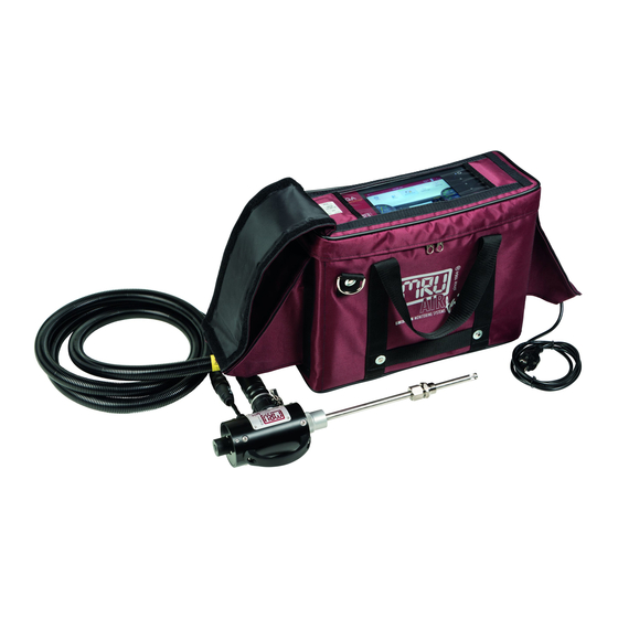
- Page 1 MGAprime Q USER MANUAL 9452EN-PRQ...
- Page 2 USER MANAUL MGAprime Q Producer: Legal notices / Intellectual property rights comments Original user manual © 2021 by MRU No part of this manual my be published in any form (print, photocopy, electronic media or any other publication form) without a written approval by the publisher.
-
Page 3: Table Of Contents
USER MANAUL MGAprime Q Table of content Information for product and safety ..........7 1.1. Safety manual ....................7 1.2. Safety precautions ..................7 Introduction ..................8 2.1. Intended use ....................9 2.2. About us ......................11 Description ..................12 3.1. - Page 4 USER MANAUL MGAprime Q Measurement .................. 31 6.1. Prepare measurement................31 Operating temperature ..................31 Power supply ......................31 Opening the transport bag ................32 Connections to the analyser ................32 Switch-on, warm-up phase, zero point ............33 Attach clip-on filter .................... 34 Controlling Filters ....................
- Page 5 USER MANAUL MGAprime Q 8.9. Analog output setup (4 – 20 mA) ............60 Setting channel ....................60 Setting lower / higher limit ................61 Setting Analog outputs during zeroing ............. 62 Pin assignment of the 4-20 mA interface (Analog IN/OUT) ....63 8.10.
- Page 6 USER MANAUL MGAprime Q 16.4. Screw adapter onto HPI-Probe (Option) ..........88 16.5. Connecting analyser with MRU4win ............ 89 Connecting analyzer with MRU4win via serial interface (RS 485)..89 Connecting analyzer with MRU4win via TCP/IP connection ....89 Creating analyzer in MRU4win ..............91 16.6.
-
Page 7: Information For Product And Safety
USER MANAUL MGAprime Q Information for product and safety 1.1. Safety manual All general information and safety precautions of MRU products are listed in the supplied separate safety manual. All information and safety precautions for the analyser MGAprime in the Safety Manual also apply to the analyser MGAprime Q. -
Page 8: Introduction
USER MANAUL MGAprime Q Introduction • Read and observe the separately supplied Safety manual. • This manual enables you to understand and safely operate this MRU Analyzer MGAprime Q. • Please read this manual with great vigilant • Get familiar with the product before using it. -
Page 9: Intended Use
USER MANAUL MGAprime Q 2.1. Intended use The analyser MGAprime Q is proofed according to DIN EN 15267-4. The following table lists proofed and non-proofed measured values. Measured variables Proofed according to Notes and conversions. 15267-4 ... - Page 10 USER MANAUL MGAprime Q The Analyzer is designed for the gas analysis of flue gases, MGAprime-Q as they are emitted from gas/oil burners, engines, or heating and power appliances. The analyser is intended to support the user in control and indicative measurements in an efficient, accurate and reliable way.
-
Page 11: About Us
USER MANAUL MGAprime Q 2.2. About us The analyser is produced by the MRU GmbH in Neckarsulm, Germany (Founded in 1984), a medium sized company that is specialised in developing, producing and marketing high quality emission monitoring analysers. MRU GmbH produces a wide range of instruments, from standard analysers up to tailor made industrial analysers. -
Page 12: Description
USER MANAUL MGAprime Q Description 3.1. Task The main task of the analyser is to analyse flue gases, as they are emit- ting from incinerators or engines. • The analyser is optimized for this purpose and includes all com- ponents from the gas sampling probe to data processing. -
Page 13: Analyser
USER MANAUL MGAprime Q Sample gas filter (PTFE) Dust filter Auto-zero solenoid valve Sample gas pump Double stage gas cooler Sample flow sensor Paramagnetic oxygen sensor Acrodisc PTFE filter Infrared (NDIR) bank Diff. pressure sensor 3.3. Analyser The Analyser consists of a compact and robust metal housing with shock-absorbing rubber corners. -
Page 14: Connectors
USER MANAUL MGAprime Q 3.4. Connectors Front side right Loudspeaker Ethernet (LAN) USB socket Second USB socket (option) RS485 (Option) Analog outputs 4 ... 20 mA Analog-inputs 4 … 20 mA Mains power supply Front side left Sample gas filter... - Page 15 USER MANAUL MGAprime Q The connection drawings are also displayed in the menu Extras. ► Touch the menu Extras. A selection list appears. ► Press „Connections“. The left side of the analyser appears. ► Push „Right >>“. The right side of the analyser appears.
-
Page 16: Heated Gas Sampling Probe
USER MANAUL MGAprime Q 3.5. Heated Gas sampling probe For interchangeable probe tube with flue gas temperature measure- ment using type K-thermoelement. Probe handle Probe tube Fast locking coupling Probe cone Cable plug (14-pin) Heated hose line Cable coupler (5-pin) -
Page 17: Gas Conditioning
USER MANAUL MGAprime Q ATTENTION When measuring with coiled heated hose line, the hose line is destroyed due to strong heat development. ► Roll out the heated hose line completely for each measurement. NOTE Please note that heating hoses with 110V and 230V are offered. -
Page 18: Gas Sensors
USER MANAUL MGAprime Q If the flow does not reach the nominal value despite an increase of the pump capacity, the pump is switched off after a while to protect the analyser. 3.8. Gas sensors The analyser has two types of gas sensors: 1. - Page 19 USER MANAUL MGAprime Q The injection of phosphoric acid (10 %) is necessary for a correct measurement. • The injection guarantees constant conditions in the gas cooler, so that you can measure dry or humid flue gas. • The use of phosphoric acid (10%) reduces losses of SO , NO the humid surfaces of the gas cooler.
-
Page 20: Operation
USER MANAUL MGAprime Q Operation 4.1. Commissioning The analyser leaves the factory assembled and ready for use. ► Check the analyser regarding completeness and integrity. ► Connect the analyser to the mains. The analyser switches on. The operating system boots. -
Page 21: Charging The Battery
USER MANAUL MGAprime Q Power-on / off not used not used LED display mains opera- tion/battery charging mode not used Current flow rate Current pump load Current temperatures heated hose Selected measuring pro- gram, e.g. Test or measure- ment program... -
Page 22: Switching On The Analyser
USER MANAUL MGAprime Q NOTE Note that the analyser can only be used in battery operation to a limited extent. ► Do not carry out any measurements in battery mode. ► Carry out only data processing and setting work in battery operation. -
Page 23: Set The Analyser To Standby Mode
USER MANAUL MGAprime Q ► Touch The display turns. 4.7. Set the analyser to standby mode The analyser is protected in standby mode. You cannot take measurements in standby mode. The actuators, for example pumps and gas coolers, are switched off as far as possible. -
Page 24: Back To Homescreen / Back To Measure
USER MANAUL MGAprime Q ► Press OK. The analyser is heated up. ► If necessary, perform a new zeroing. 4.8. Back to homescreen / Back to measure As soon as the back button is displayed, you have the option to go back to the homescreen or go back to the measurement, from any window. -
Page 25: Settings
USER MANAUL MGAprime Q Settings After the analyser has been inspected and is ready for start-up it can be switched on and personalized settings can be entered. These settings can be changed at any time. 5.1. Analyser settings In the Settings menu, some analyser pre-sets may be configured: ►... - Page 26 USER MANAUL MGAprime Q For an overview on all available options please refer to the company’s home page or sales representatives Country (fuel type) By changing the country, the O refer- ence values settings are lost. The fuel list is reset. Similarly, country-specific de- faults and methods of measurement are selected as a result.
-
Page 27: Setting Time And Date
USER MANAUL MGAprime Q 5.2. Setting time and date In the menu Extras, you can check the date and time and, if necessary, set it. When connected to the Internet, the time automatically synchronizes itself. ► Touch the menu Extras. -
Page 28: Further Measuring Programs
USER MANAUL MGAprime Q Further measuring programs The measurement window for gas analysis can be configured and adapted to your needs. The measuring window initially displays 12 measured values, by a scrolling gesture it will display more values. Moving a value field ►... -
Page 29: Setting Zoom
USER MANAUL MGAprime Q You can insert the selected measured value in place of the se- lected value field. The previously selected value field moves accordingly. ► Touch „replace“ or „insert“. Setting zoom ► Touch the menu Measure. The measurement window appears. - Page 30 USER MANAUL MGAprime Q ► Touch „Gas flow measurement“. A setting window appears. ► Change the desired parameters. ► Touch „CHOOSE UNITS“. A setting window appears. ► Change the desired unit. ► Go back. The change will be saved.
-
Page 31: Measurement
USER MANAUL MGAprime Q Measurement 6.1. Prepare measurement CAUTION Acid from the condensate Acid burns may result from weakly acidic liquids from the condensate. ► If you come into contact with acid, wash the area im- mediately using a lot of water. -
Page 32: Opening The Transport Bag
USER MANAUL MGAprime Q ATTENTION When measuring with coiled heated hose line, the hose line is destroyed due to strong heat development. ► Roll out the heated hose line completely for each measurement. ► Unroll the heating hose. ► Connect the heating hose. -
Page 33: Switch-On, Warm-Up Phase, Zero Point
USER MANAUL MGAprime Q ► Ensure that ambient fresh air can be sucked in at the Fresh air inlet port (11). Consider to connect a hose leading fresh air to analyser. The flow rate of the gas should be within 60ln/h. -
Page 34: Attach Clip-On Filter
USER MANAUL MGAprime Q Attach clip-on filter If you operate the analyser without a heated hose, dirt may collect in the gas inlet. ► In this case, plug the supplied clip-on filter onto the gas inlet (12). Controlling Filters The filters (probe filter and round filter) must be checked before and after each measurement. -
Page 35: Connecting Acid Dosing Unit Ape
USER MANAUL MGAprime Q Connecting Acid Dosing Unit APE See also Chapter 3.9 Acid injection, page 18. CAUTION Acid from the condensate Acid burns may result from weakly acidic liquids from the condensate. ► If you come into contact with acid, wash the area im- mediately using a lot of water. - Page 36 USER MANAUL MGAprime Q NOTE Always connect the collection container. Please note that the volume of the supplied collecting container is sufficient for 2 hours of measuring opera- tion. ► Empty the collecting container after two hours of measuring operation.
-
Page 37: Perform Leak Test
USER MANAUL MGAprime Q Perform leak test The analyser device has an integrated leak test to check the tightness of the gas paths. ► Check all plug connections for correct fit. ► Check all hoses and hose connections (from the probe tip to the gas inlet of the analyser) for leaks. - Page 38 USER MANAUL MGAprime Q NOTE Please note that no leak test can be performed with a connected Acid Dosing Unit APE. The Acid Dosing Unit APE is connected to the analyser via a connecting hose with two couplings. ► Remove the two couplings from the analyser.
-
Page 39: Repeated Zero Point
USER MANAUL MGAprime Q after you have performed the leak test. Repeated Zero point Authorized persons can start a new zeroing after entering the pin code. See also chapter 10 Entering Pin code, Page 73. ► Touch the menu Measure. -
Page 40: Take A Measurement
USER MANAUL MGAprime Q From 2% remaining capacity, the charging indicator starts to flash red. If the instrument is not connected to the mains power supply within one minute, the analyser switches off to prevent battery discharge. Even when the battery is discharged, the instrument can be operated completely on the power supply. -
Page 41: Storing Measured Values
USER MANAUL MGAprime Q ► Set the desired O2 reference [%]. ► Press OK. The set O2 reference [%] is adopted. Storing measured values You can assign the measured values to the corresponding site and save them. ► Touch the menu Measure. - Page 42 USER MANAUL MGAprime Q ► Touch the display. ► Move the window to the left. The window with "Recorded channels" appears. ► Press a measurand that you want to replace. A window appears. ► Select the desired measurand.
- Page 43 USER MANAUL MGAprime Q ► Press the graphic symbol. A diagram appears. ► If necessary, touch to stop the graphical display. The measurement will be continued in the background. ► If necessary, touch to continue the graphical display. 43 / 98...
-
Page 44: Starting Auto-Measurement
USER MANAUL MGAprime Q Starting Auto-measurement You can record the measured values for a defined period and have them displayed graphically. ► Touch the menu Measure. The measurement window appears. ► Touch the “Context menu” (19). A selection list appears. - Page 45 USER MANAUL MGAprime Q ► Touch „OK “ The window „Please select site“ appears. ► Select the desired site. The Auto-measurement starts automatically. The Auto-measurement ends automatically. A protocol of the Auto-measurement appears ► Press the graphic symbol.
-
Page 46: Stopping Auto-Measurement
USER MANAUL MGAprime Q ► Select Export CSV or Print. The data is exported or printed See also chapter 8.8 Internal log Settings, page 57. Stopping Auto-measurement The Auto-measurement can be stopped manually at any time. ► Touch the context menu (19) while the measurement is recorded. -
Page 47: Data Storage
USER MANAUL MGAprime Q Data storage 7.1. Organizing data storage Base of the data memory of the analyser is a set of sites stored in the instrument. Every site exists of a unique site number and 12 freely usa- ble text lines which can have, e.g., the address, customer name etc. -
Page 48: Changing Site Data
USER MANAUL MGAprime Q ► Enter the site data. ► Touch „SAVE“. The site is saved. Changing site data ► Touch the menu Sites. A selection list appears. ► Select the desired site. A window appears. ► Change the desired data. -
Page 49: Deleting Sites
USER MANAUL MGAprime Q Deleting sites ► Touch the menu Sites. A selection list appears. ► Select the desired site. A window appears. ► Touch „Delete“. The site is deleted. Recalling stored measurements Stored measurement can be displayed individually for each site. -
Page 50: Data Transfer Via Usb (Csv Export)
USER MANAUL MGAprime Q ► Touch „MEASUREMENTS“. A selection list appears. ► Touch the desired measurement. The measurement window appears. 7.3. Data transfer via USB (CSV export) The data exchange format is CSV. A character-separated values (CSV) file is a simple text format for a database table. The analyser uses a sem- icolon ‘;’... - Page 51 USER MANAUL MGAprime Q ► Insert a USB-stick into the analyser. ► Touch the menu Sites. A selection list appears. ► Select the desired site. A window appears. ► Touch „MEASUREMENTS“. The stored measurements are displayed. ► Select the desired measurements.
- Page 52 USER MANAUL MGAprime Q ► Open the CSV-File with Excel. (Do not use Dat-files files or internal Log-files) 52 / 98 MRU GmbH, D-74172 Neckarsulm...
-
Page 53: Extras
USER MANAUL MGAprime Q Extras 8.1. History ► Touch the menu Extras. A selection list appears. ► Touch „History“. A window appears. Touch „DATE“. A selection list appears. ► Choose the desired period time. 53 / 98... -
Page 54: System Extensions
USER MANAUL MGAprime Q The chosen time period is displayed graphically. 8.2. System extensions You have the possibility to expand the analyser with options. For this you will receive an option file from the manufacturer. ► Copy the options file onto a USB stick. -
Page 55: Connections
USER MANAUL MGAprime Q ► Select the desired Options. ► Press “LOAD CHECKED OPTIONS”. A message appears. ► Touch OK. The option was successfully set. 8.3. Connections You can view the connections on the display of the analyser. -
Page 56: Instrument Leak Test
USER MANAUL MGAprime Q ► Exit the Extras menu. ► Touch Selected measuring program (8) See also Chapter 4.2 Operating panel, Page 20. The changed Program name is shown in the display. 8.6. Instrument leak test You can perform an Instrument leak test. -
Page 57: Internal Log Settings
USER MANAUL MGAprime Q ► Press OK. The analyser is reset to factory default. 8.8. Internal log Settings The analyser stores internal parameters at regular intervals to allow for an optimized support from experienced service staff. These files can be copied to a connected USB stick and sent via email if required to do so. -
Page 58: Copying Single Log Data
USER MANAUL MGAprime Q A window appears. The copy process is started. A Symbol appears in the Display. ► Touch „OK“: The directory [serial number] Logg was created on the USB-Stick. The log files are saved in the directory [serial number]. - Page 59 USER MANAUL MGAprime Q ► Choose the desired log file. A window appears. The desired log file appears in the window. ► Touch „COPY TO EXTERN USB-STICK“. A window appears. The copy process is started. The directory [serial number] Logg was created on the USB-Stick.
-
Page 60: Analog Output Setup (4 - 20 Ma)
USER MANAUL MGAprime Q 8.9. Analog output setup (4 – 20 mA) There are 8 Analog outputs (4-20 mA) available. Each Analog output (channel) is assigned a measured variable and an output range. Setting channel ► Touch the menu Extras. -
Page 61: Setting Lower / Higher Limit
USER MANAUL MGAprime Q Setting lower / higher limit NOTE Setting lower limit (4mA) This setting determines the lower end value, corre- sponding to 4 mA. Please note that negative measured values at the Analog output lead to signals smaller than 4 mA. -
Page 62: Setting Analog Outputs During Zeroing
USER MANAUL MGAprime Q ► Touch "Default" to set the default values for the lower and upper limits. Setting Analog outputs during zeroing Zeroing starts automatically. The display shows „zero“. The remaining time until the Zero point measurement ends is displayed. -
Page 63: Pin Assignment Of The 4-20 Ma Interface (Analog In/Out)
USER MANAUL MGAprime Q The following settings are possible: •Hold - The outputs kept the last values from before zeroing •2 mA - The outputs change to 2 mA to indicate the zero point. Regard- less of the setting, 2 mA is always output during the first zero point measurement. -
Page 64: Analog Input Setup (4-20Ma)
USER MANAUL MGAprime Q 8.10. Analog input setup (4-20mA) There are 4 Analog inputs (4-20 mA) available. Each Analog input (channel) is assigned a measured variable and an output range. ► Touch the menu Extras. A selection list appears. -
Page 65: Connecting Analyser With Wifi
USER MANAUL MGAprime Q 8.11. Connecting analyser with WIFI ► Insert a WLAN stick into the analyser. ► Touch the menu Extras. A selection list appears. ► Touch “WiFi”. A window appears. ► Switch on the WLAN. The available WLAN connections are displayed. -
Page 66: Getting Information About The Network
USER MANAUL MGAprime Q A connection to the WLAN network is established. A WLAN symbol appears in the display. ► Touch the WLAN icon to see the WLAN IP. ► Alternatively, open the overview display to see the WLAN-IP. -
Page 67: Assigning A Fixed Ip Address
USER MANAUL MGAprime Q 8.13. Assigning a fixed IP address ► Touch the menu Extras. A selection list appears. ► Touch „Network“. A window appears. ► Set the switch to "Static IP is active". The fields for „IP-Adress/Subnetmask“, „Gateway“... -
Page 68: Serial Connectivity (Rs485/Usb)
USER MANAUL MGAprime Q ► Choose the desired option. The change takes effect after a restart. 8.14. Serial connectivity (RS485/USB) You have a connection option to MRU4win via Bluetooth. 8.15. Printing measurements results In the menu Printer, you can select the type of connection between an optional printer and the analyser. -
Page 69: Printing Stored Measurement Results
USER MANAUL MGAprime Q ► Touch the “Context menu” (19). A selection list appears. ► Touch „Print“. The measurement is printed out with a slight delay. Printing stored measurement results ► Switch on the printer. ► Touch the menu „Sites“. -
Page 70: Service Values
USER MANAUL MGAprime Q ► Touch the desired measurement. The measurement window appears. ► Touch the context menu (19). A selection list appears. ► Touch „Print“. The measurement is printed out with a slight delay. 8.16. Service values This screen displays a number of internal parameters and their values. -
Page 71: Access Key
USER MANAUL MGAprime Q 8.17. Access key For customer service. 71 / 98 MRU GmbH, D-74172 Neckarsulm... -
Page 72: Info
USER MANAUL MGAprime Q INFO In the menu Info, version information and installed options can be viewed. ► Touch menu info. A window appears. ► Touch „INFO“. A window appears. ► Touch „OPTIONS“. A window appears. 72 / 98... -
Page 73: Entering Pin Code
USER MANAUL MGAprime Q 10 Entering Pin code Entering a password enables authorized personnel to calibrate the sen- sors. The password is available from the producer on request. Not required for regular operation of the analyser. Manual calibration of O2 is not possible. -
Page 74: Calibrating Ndir Cuvette
USER MANAUL MGAprime Q 11 Calibrating NDIR cuvette The zero point of the NDIR measuring channels is taken at the end of the warm-up phase after switching on the analyser (or manually trig- gered after entering a PIN code). The user has the possibility to carry out a reference point calibration by feeding test gas. -
Page 75: Calibrating Ndir Reference Points
USER MANAUL MGAprime Q 11.2. Calibrating NDIR reference points The following steps show the calibration procedure for an NDIR cuvette in the analyser: The calibration menu can be opened in the menu NDIR 1096. ► Open the menu. ► To enter the calibration menu of the cuvette, a PIN must be entered. -
Page 76: Reference Point Calibration
USER MANAUL MGAprime Q 1.Gas 2. Current measured value 3. Setpoint for the measuring channel (in this example N0 50ppm). Reference point calibration ► Connect the sample gas cylinder to the analyser. See also Chapter 11.1 Connecting analyser to sample gas cylin- der, Page 74. -
Page 77: Maintenance And Cleaning
USER MANAUL MGAprime Q 12 Maintenance and cleaning 12.1. Cleaning and maintenance The analyser needs only low maintenance effort for long value preservation: CAUTION Acid from the condensate Acid burns may result from weakly acidic liquids from the condensate. ► If you come into contact with acid, wash the area im- mediately using a lot of water. -
Page 78: Transport And Storage
USER MANAUL MGAprime Q 13 Transport and storage If the analyser is transported or stored, you must take special precautions: ► Only transport and store the analyser in the transportation bag pro- vided ► Avoid shocks when transporting the analyser. -
Page 79: Simple Service Work
USER MANAUL MGAprime Q 14 Simple service work 14.1. Information of the analyser components Information about analyser components is helpful in case of service or inquiries. ► Touch A selection list appears. ► Choose the desired component of the analyser. - Page 80 USER MANAUL MGAprime Q A selection list appears. ► Touch „Software update”. A window appears. ► Touch „LOAD FROM USB-STICK“. The firmware is copied to the analyser. The button"PERFORM FIRMWARE UPDATE" becomes active when the copy process is complete.
-
Page 81: Specifications
USER MANAUL MGAprime Q 15 Specifications 15.1. Specifications of NDIR technology T90 / s Measuring Range Certification range / Resolution Repeatability 8h-Drift Linearity 0 - min ... max additional range 0 - 200...4.000 ppm 0 - 200 / 2.000 ppm 0,1 ppm 2ppm / 1% rdg. -
Page 82: Sensors For Oxygen, Temperatures And Pressure
USER MANAUL MGAprime Q 15.2. Sensors for Oxygen, Temperatures and Pressure Paramagnetic Sensor Measuring Range O - 25 Vol% Resolution 0,01 Vol% Accuracy 0,1 Vol% Flue gas temperature Measuring Range with high grade 0 – 800° C steel probe pipe Measuring range with Inconel probe 0 –... -
Page 83: Calculated Values And Accessories
USER MANAUL MGAprime Q 15.4. Calculated values and accessories Measurement values available as mg/Nm mg/kWh NOx: mg/Nm Velocity based on differential pressure meas- urement with Pitot tube Typical measuring range 3 m/s ... 100 m/s Accuracy at 3m/s. 1 m/s Accuracy >... -
Page 84: Technical Data Acid Dosing Unit Ape
USER MANAUL MGAprime Q Weight incl. Case 15,0 kg Size incl. Case (WxHxD) 46cm x 33 cm x 20 cm Housing Material Aluminium / TPU Material Protection Bag Nylon IP degree of protection incl. protection bag IP42 15.7. Technical data Acid Dosing Unit APE Operating temperature +5°C ... -
Page 85: Appendix
USER MANAUL MGAprime Q 16 Appendix 16.1. Error diagnosis regarding the measuring instrument Fault indication Possible causes Repair Gas cooler is faulty! Gas cooler faulty. Contact MRU service depart- The system will shut ment. down. Undervoltage!!! Battery is discharged. Connect instrument to power The System will shut grid. - Page 86 USER MANAUL MGAprime Q Fault indication Possible causes Repair Condensate or wa- ► To continue the operation it has to be en- ter has been de- sured that no water will be fed to the sen- tected behind the sors.
-
Page 87: Switching Off The Analyser In Case Error
USER MANAUL MGAprime Q 16.2. Switching off the analyser in case error If the touch screen does not respond, you have two options for switch- ing off the analyser: ► Touch the ⏻ button during flashing LED for 30 sec. minimum ►... -
Page 88: Screw Adapter Onto Hpi-Probe (Option)
F 32 bit floating point value (reads -1E38, when not availa- ble)- Further information about the defined registers on demand (www.mru.eu) and on the device supplied USB stick! 16.4. Screw adapter onto HPI-Probe (Option) With the adapter you have the possibility to use heated probe tubes from other manufacturers. -
Page 89: Connecting Analyser With Mru4Win
USER MANAUL MGAprime Q 16.5. Connecting analyser with MRU4win The analyser is a Modbus device. ► You can connect Modbus devices with MRU4win via a serial interface (RS 485). See also Chapter 16.3 RS485 Extern (Option), Page 87. ► You can connect Modbus devices to MRU4win via a TCP/IP connection. - Page 90 USER MANAUL MGAprime Q A selection list appears. ► Touch “Display settings”. An overview screen appears. In the top line, the IP address of the analyser is displayed. In this example the LAN address is 192.168.44.38. ► Switch to the Settings menu.
-
Page 91: Creating Analyzer In Mru4Win
USER MANAUL MGAprime Q Creating analyzer in MRU4win Modbus devices are not automatically identified in MRU4win. Before you can the analyser with MRU4win, you have to create a Modbus device. ► Open MRU4win. ► Set under Settings "General” a check mark at "Activate Modbus". - Page 92 USER MANAUL MGAprime Q ► Choose “Name” A selection list appears. ► Choose “1113 Device”. ► Set "Slave ID" to 1. Note that the slave ID must match to the "Modbus Slave ID" of the analyser. For example, if the analyser has the "Modbus Slave ID" 2, the "Slave ID"...
-
Page 93: Remote Control Of The Analyser Device Via Vnc
USER MANAUL MGAprime Q ► Click on the "Connect-Icon” The analyser is connected. 16.6. Remote control of the analyser device via VNC Activate WLAN-Hotspot (android) ► Install VNC viewer ► ► Configure VNC viewer Connect to device ► Activate VNC on Analyzer ►... -
Page 94: Cxhy Calculation
USER MANAUL MGAprime Q ► Use remote control via Android device NOTE Please note that due to the increased computing power, the CPU temperature will increase. If the tem- perature should become too high, the VNC server switches off automatically. -
Page 95: Unrolling The Heated Hose Line
USER MANAUL MGAprime Q Unrolling the heated hose line A wrong and careless use of the heated hose line may cause damage. Especially on very long heated hose lines the right unpacking and roll- ing out is important. Right Wrong... -
Page 96: Bending Radius Of Heated Sampling Lines
USER MANAUL MGAprime Q Bending radius of heated sampling lines The picture below shows the minimal bending radius. Bending radius min. = 32 ATTENTION Falling below the bending radius will reduce life time of the sampling probe. 16.9. Spare parts... -
Page 97: Declaration Of Conformity
USER MANAUL MGAprime Q 17 Declaration of conformity 97 / 98 MRU GmbH, D-74172 Neckarsulm... - Page 98 USER MANAUL MGAprime Q 98 / 98 MRU GmbH, D-74172 Neckarsulm...
Need help?
Do you have a question about the MGAprime Q and is the answer not in the manual?
Questions and answers