Table of Contents
Advertisement
Quick Links
Advertisement
Table of Contents

Related Manuals for Airlink101 AR695W


Summary of Contents for Airlink101 AR695W
- Page 1 Wireless N 300 Gigabit Green Router Model # AR695W User’s Manual Ver. 1A...
-
Page 2: Fcc Interference Statement
Copyright Copyright © Airlink101, 2010. The contents of this publication may not be reproduced in any part or as a whole, stored, transcribed in an information retrieval system, translated into any language, or transmitted in any form or by any means, mechanical, magnetic, electronic, optical, photocopying, manual, or otherwise, without the prior written permission. -
Page 3: Table Of Contents
CHAPTER 1 PRODUCT INFORMATION...1 1.1 I NTRODUCTION AND SAFETY INFORMATION 1.2 P ...2 ACKAGE ONTENTS 1.3 F AMILIAR WITH YOUR NEW CHAPTER 2 CONFIGURE THE ROUTER ...5 2.1 C ONNECT THE OUTER TO YOUR NETWORK 2.2 C ONFIGURE THE OUTER WITH 2.3 C ONFIGURE THE OUTER WITH... - Page 4 3.4.7 Schedule Rule...83 3.5 T ...85 OOLBOX 3.5.1 View Log...86 3.5.2 Firmware Upgrade...87 3.5.3 Backup Setting...88 3.5.4 Reset to Default...88 3.5.5 Reboot ...89 3.5.6 Miscellaneous...89 CHAPTER 4 STATUS...91 4.1 S ...92 YSTEM TATUS 4.2 W ...92 IRELESS TATUS 4.3 S ...93 TATISTICS NFORMATION...
-
Page 5: Chapter 1 Product Information
WPA2-PSK provide the highest level of wireless network security. The bundled EZ Setup Wizard allows you to set up the router with an easy-to-use user interface. Best of all, AR695W works with all 802.11n / g / b network devices which ensures compatibility with your existing wireless products. -
Page 6: Package Contents
1.2 Package Contents Before you start using this router, please check if there’s anything missing in the package, and contact your dealer of purchase to claim for missing items: 1. Wireless N 300 Gigabit Green Router 2. Two Antennas 3. Power Adapter 4. -
Page 7: Familiar With Your New Gigabit Router
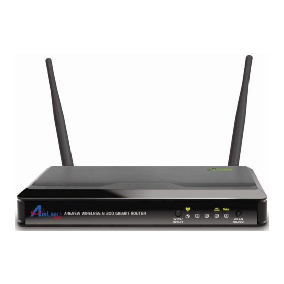
1.3 Familiar with your new Gigabit Router A. Front Panel Status Status Blinking (Green) On (Green) On/Sleep On (Green) Blinking On (Green) LAN 1~4 Blinking On (Green) Blinking Wireless Blinking Rapidly Button Description Reset router to factory default settings or start security synchronization function (WPS). - Page 8 B. Back Panel Item Name Description Antennas These antennas are detachable 3dBi dipole antennas. ON/OFF Switch on/off the router. 1 - 4 Local Area Network (LAN) ports 1 to 4. Wide Area Network (WAN / Internet) port. Power connector, connects to A/C power adapter.
-
Page 9: Chapter 2 Configure The Router
Chapter 2 Configure the Router 2.1 Connect the Router to your network Note: Prior to connecting the router, be sure to power off your computer, DSL/Cable modem, and the router. Connect one end of a network cable to the WAN port of the router and connect Step 1 the other end of the cable to the DSL/Cable modem. - Page 10 Plug the power adapter to the router and connect it to an electrical outlet. Make Step 4 sure the power switch at the back is “On”. Power on your computer. Step 5 Check LEDs of the router: make sure Status, WAN, Wireless, and the LAN port Step 6 that the computer is connected to are lit.
-
Page 11: Configure The Router With Ez Setup Wizard
2.2 Configure the Router with EZ Setup Wizard Insert the Setup CD into CD-ROM drive. Step 1 When the autorun menu pops up, click EZ Setup Wizard. Step 2 Note: If the autorun menu does not show up on your monitor, please go to Computer CDROM drive Wizard, and execute “EZWizard.exe”. - Page 12 Select your language and click Next. Step 3 Click on Wizard. Step 4...
- Page 13 Please make sure your computer is connected to the LAN port of the router, and Step 5 your modem is connected to the WAN port of the router. Click Next to configure the basic wireless settings. Step 6...
- Page 14 Configure the SSID (wireless network name, i.e. myHome), Channel, Security Step 7 and Key. It is suggested to select WPA2-PSK for best wireless security. Enter 8~63 characters into Key box, then click Next. Click Next and the wizard will detect your WAN settings, or you can select your Step 8 WAN type manually by checking “Let me select WAN service by myself”.
- Page 15 Enter the settings based on your WAN service type. Step 9 Cable (Dynamic IP) If you are using cable Internet service, your WAN type is “Dynamic IP”. You do not need to configure anything here, then click Next to continue. DSL (PPPoE or Dynamic IP) For DSL users, your WAN type is either PPPoE or Dynamic IP.
- Page 16 For PPPoE settings, please enter the username and password provided by your ISP (Internet Service Provider). Note: Depending on the ISP, you may need to include the domain name with your username. Example: username@sbcglobal.net Verify the settings you have configured. Click Next to save the settings and Step 10 reboot the router.
- Page 17 Click Next to test the Internet Connection, or you can ignore the test, just open Step 11 the Internet browser and verify if you are connected to the Internet. If you cannot connect to the Internet, please go to Section 4, Troubleshooting. After the WAN service test completed, click Finish.
- Page 18 You will see the status of the router on the web configuration page brought up by the web browser. Valid numbers should be assigned to IP Address, Subnet Mask and Gateway, instead of all 0’s.
-
Page 19: Configure The Router With Web Configuration Utility
2.3 Configure the Router with Web Configuration Utility Another approach to configure the router is using the Wizard in the Web Configuration Utility. The wizard will guide you setting up the basic settings of this router. You do not need to go through the wizard again if you have finished 2.2 Configure the Router with EZ Setup Wizard. - Page 21 Click Next to start the Setup Wizard. Step 4 Change System Password. Enter the current password, new password and Step 5 reconfirm the new password. (The default password is ‘admin’.) If you do not wish to change the password, please leave all fields blank. Click Next.
- Page 22 Select Auto Detecting WAN Type to let the wizard detect which Internet Step 6 connection you use or select Setup WAN Type Manually to select the Internet connection type manually. Click Next. If you select Setup WAN Type Manually, please specify a WAN type you are using. For Cable Users: Please select Obtain an IP address from ISP automatically (Dynamic IP Address).
- Page 23 Address) or Some ISPs require the use of PPPoE to connect to their services (PPP over Ethernet) depending on the type of modem provided by your ISP (Internet Service Provider). You can try both settings and determine which one works for you. Click Next.
- Page 24 Enter the Account and Password provided by your ISP. PPP over Ethernet: Note: Depending on the ISP, you may need to include the domain name with your username. Example: username@sbcglobal.net Keep the default SSID (wireless network name) or change it to a desired name, Step 8 so you can always recognize your wireless network with it, for example ‘myHome’.
- Page 25 Set up Wireless Security for your router. It is recommended to select WPA2-PSK Step 9 (AES) for security to protect your wireless network from unauthorized users. Type in 8~63 characters into Preshare Key. Click Next. WPA2-PSK (AES) is the most secured encryption mode for general users but some older wireless adapters might not support it.
- Page 26 Verify the information you have configured. If everything is correct, click Apply Step 10 Settings to save the settings and reboot router. When you see window like below, you are successfully connected to the Internet. Step 11 Click Finish. Congratulations! Your router configuration has been finished. Please go to 2.4 Connect to the Router Wirelessly.
-
Page 27: Connect To Router Wirelessly
2.4 Connect to Router Wirelessly You must configure your wireless computer in order to establish a wireless connection to the router. In this section, you can find the instructions of how to connect to the router wirelessly with your Windows 7 computer. You can also refer to the manual of your wireless device on how to connect to the router. - Page 28 Enter the key you configured for the router if you have enabled the wireless Step 2 security, then click OK. The wireless connection should be now established.
-
Page 29: Chapter 3 Advanced Configuration
Chapter 3 Advanced Configuration You can make advanced configurations on this router through Web Configuration Utility to meet your network’s needs, such as: Virtual Server, Access Control, Network Security, etc. If you have already gone through the Setup Wizard, you do NOT need to configure anything here for you to start using the Internet. -
Page 31: Basic Setting
3.1 Basic Setting You can configure LAN, Internet connection type, DHCP, wireless settings and system password for the router in this page. -
Page 32: Primary Setup
3.1.1 Primary Setup This page allows you to specify an IP address for your router, and configure the Internet connection settings. Parameter LAN IP Address WAN Type IGMP Virtual Computers 3.1.1.1 WAN Type If you need to change router’s WAN type, please click Change in the Primary Setup menu. - Page 33 Select a WAN type from the list and click Save. A. Static IP Address: Click on Static IP Address if your ISP (Internet Service Provider) has provided you a set of IP addresses for your Internet connection. B. Dynamic IP Address: Click on Dynamic IP if you are connecting to Internet through a cable modem.
- Page 34 A) Static IP Address Enter the WAN IP address, WAN Subnet Mask, WAN Gateway, Primary DNS , and Secondary DNS addresses provided by your ISP. After you finished all settings, click Save to save the settings and click Reboot. The change will take effect after rebooting the router.
- Page 35 Parameter Host Name WAN’s MAC Address Renew IP Forever After you finished all settings, click Save to save the settings and click Reboot. The change will take effect after rebooting the router. Description Please input the host name of your router; this is optional and only required if your service provider asks you to do so.
- Page 36 C) Dynamic IP Address with Road Runner Session Management: Please enter the account and password provided by your Telstra Big Pond ISP. Parameter Account Password Login Server After you finished all settings, click Save to save the settings and click Reboot. The change will take effect after rebooting the router.
- Page 37 D) PPP Over Ethernet (PPPoE) Parameter PPPoE Account PPPoE Password Primary DNS Secondary DNS Maximum Idle Time Connection Control Description Enter the User Name for your DSL account, you can obtain this information from your ISP. Enter the Password for your DSL account, you can obtain this information from your ISP.
- Page 38 PPPoE Service Name Assigned IP Address MTU (Maximum Transmission Unit) After you finished all settings, click Save to save the settings and click Reboot. The change will take effect after rebooting the router. E) PPTP to the ISP after the connection is established. Manually: Router will not connect to the ISP until user clicks the Connect button on the Status-page.
- Page 39 Parameter IP Mode My IP Address My Subnet Mask Gateway IP Server IP Address/Name PPTP Account PPTP Password Connection ID Maximum Idle Time Connection Control Maximum Transmission Unit (MTU) Description Select the type of how you obtain IP address from your service provider here: Static IP Address or Dynamic IP Address.
- Page 40 E) L2TP Parameter IP Mode My IP Address My Subnet Mask Gateway IP Server IP Address/Name L2TP Account L2TP Password Maximum Idle Time Description Select the type of how you obtain IP address from your service provider here: Static IP Address or Dynamic IP Address. Enter the IP address assigned by your ISP if you select Static IP Address.
-
Page 41: Virtual Computers
Connection Control Maximum Transmission Unit (MTU) 3.1.1.2 Virtual Computers Virtual Computer enables you to use the original NAT feature, and allows you to set up the one-to-one mapping of multiple global IP addresses and local IP addresses. Parameter Global IP Local IP Enable session. -
Page 42: Dhcp Server
3.1.2 DHCP Server This page allows you to configure the DHCP settings for your router. Parameter DHCP Server Lease Time IP Pool Starting/Ending Address Domain Name Press “More>>” for more options Description Select Disable or Enable the DHCP server. DHCP lease time to the DHCP client. Please enter a number between 5 to 10080. - Page 43 Primary DNS/Secondary DNS Primary WINS/Secondary WINS Gateway Client List Click Save to save the settings you made. This is optional. This feature allows you to assign a Primary / Secondary DNS Server. This is optional. This feature allows you to assign a WINS Server. This is optional.
-
Page 44: Wireless
3.1.3 Wireless You can set parameters that are used for wireless clients to connect to this router. The parameters include SSID, Channel Number, Encryption etc. Parameters Default Enable Wireless Disable Wireless On/Off by Time schedule Schedule Setting Airlink101 Network ID (SSID) Description Enable or disable wireless function. - Page 45 11b/g/n mixed Wireless Mode Enable SSID Broadcast Channel Security Wireless Client List routers in the same area. It’s recommended to change default SSID value to the one which is meaningful to you, like myhome, office_room1, etc. Please select the wireless mode from one of the following options: 11b/g/n mixed: 2.4GHz band, allows 802.11b, 802.11g, and 802.11n wireless network clients to connect to this...
- Page 46 Configuring Security - WEP Note: IEEE802.11n only supports WPA2-PSK or WPA-PSK AES encryption. If you use WEP as your encryption, wireless data rate will drop to 54Mbps (802.11g standard). Select HEX or ASCII. You can select ASCII (alphanumeric format) or Key Mode: Hexadecimal (in the “a~f”...
- Page 47 communication, so the encryption key is not easy to be broken by hackers. This can greatly improve your wireless security.WPA2-PSK AES is the most secured setting for general users. Select WPA-PSK or WPA2-PSK Security: Select either AES or TKIP. It is suggested to select AES if all your Encryption: wireless computers / devices support this encryption mode.
- Page 48 Encryption Key Length: You can select either 64 bits or 128 bits. RADIUS Server IP: The RADIUS server's IP address. RADIUS port: The RADIUS server's service port. RADIUS Shared Key: Key value shared by the RADIUS server and this router. This key value should be consistent with the one in the RADIUS server.
- Page 49 With the WDS feature, the Wireless LAN coverage can be easily extended. Note: WDS-enabled routers or APs from different manufacturers are not guarantee to work with AR695W. It is recommended to deploy WDS with solely Airlink101 AR695W.
- Page 50 Enter the MAC address of other WDS enabled AP/Router into MAC 1 ~ MAC4. This feature allows you to bridge up to 4 AR695W routers. It is suggested to use “Copy to” function to avoid any typo. Click on the drop-down menu to select a AP you wish to bridge...
- Page 51 3.1.3.2 WPS (Easy Setup Button) The AR695W Wireless N 300 Gigabit Green Router has a built-in Easy Setup Button (WPS) which allows you to build secured wireless connection between your wireless computers and the router quickly and easily. Please make sure your wireless device support this feature as well.
- Page 52 Within the following 2 minutes, push the WPS Button on the Router and hold for 1 Step 3 second. The wireless LED will start blinking quickly. The Router will now start the handshake with the wireless adapter which will take Step 4 about 30 seconds.
- Page 53 To configure the WPS settings of the router, go to Advanced > Basic Setting > Wireless, then click on WPS button. There are two methods to activate WPS – PIN and PBC. 1) PIN (Personal Identification Number) You can choose to enter the numbers generated by this router displaying in “Current PIN of the device”...
- Page 54 enter the PIN generated by the wireless client computer into Enrollee PIN, and click Trigger button to start WPS. 2) PBC (Push Button Configuration) You can choose to press the hardware button on the front panel of the router, or select Configure Wireless Station, Software button, and click Trigger button to start WPS.
-
Page 55: Wireless Client List
WPS State WPS Status Click Save after you finished all settings. 3.1.3.3 Wireless Client List This table displays the wireless clients that are currently associated to the router. You can click Back to go back to the Wireless page, or click Refresh to refresh the list. It displays “Idle”... -
Page 56: Change Password
3.1.4 Change Password You can change the password required to log in to the Router’s web configuration utility. The default password is “admin”. It is suggested to change the administrator’s default password as soon as you start to use the Router, and store it in a safe place. The password consists of 0 to 9 alphanumeric characters, and is case sensitive Parameters Old Password... -
Page 57: Forwarding Rules
3.2 Forwarding Rules 3.2.1 Virtual Server If you want to host a HTTP/FTP server or allow remote access to your IP camera on the LAN from the Internet, you must set up port forwarding rules on the router in order to direct incoming traffic to the server or IP Camera. - Page 58 Protocol Enable Schedule Rule# Next>> / Previous<< Click Save after you finished all settings. This is the protocol type to be forwarded. You can choose to forward “TCP” or “UDP” packets only or select “Both” to forward both “TCP” and “UDP” packets. Check to enable this forwarding rule.
-
Page 59: Special Applications
3.2.2 Special Applications Some applications require multiple connections, such as Internet gaming, video conferencing, Internet telephony and others. These applications cannot work when Network Address Translation (NAT) is enabled. If you need to run applications that require multiple connections, specify the port normally associated with an application in the “Trigger”... -
Page 60: Miscellaneous
Note: Only one PC can use each Special Application tunnel at same time. If the mechanism of Special Applications fails to make an application work, try setting your computer as the DMZ host instead. Click Save after you finished all settings. 3.2.3 Miscellaneous If you have a local client PC that cannot run an Internet application (e.g. - Page 61 Super DMZ (IP Passthrough) Non-standard FTP Port UPnP Xbox Support Click Save after you finished all settings. Select Super DMZ when your computer or server on the Local Area Network needs to allow access from the Internet with a real public IP address.
-
Page 62: Security Setting
3.3 Security Setting This function allows you to configure Internet access rules for your local computers based on the IP address, MAC address, URL or keywords. 3.3.1 Packet Filtering Packet Filtering allows you to control access to a network by analyzing the incoming and outgoing packets and letting them pass or halting them based on the IP address of the source and destination. - Page 63 Computers with IP addresses between 192.168.2.20 to 192.168.2.50 have no restriction on accessing any network services, while others computers are all blocked. Meanwhile, computers with IP addresses between 192.168.2.100 to 192.168.2.199 are allowed to send Email (port 25), receive E-mail (port 110), and browse Internet (port 80). For each rule, you can define: Source IP address •...
- Page 64 Port Enable Schedule Rule# Inbound Filter Click on Save after you finished all settings. Please input the port number here. You can define a single port (80) or a range of ports (1000-1999). Add prefix "T" or "U" to specify TCP or UDP protocol, for example, T80, U53, U2000-2999.
-
Page 65: Domain Blocking
3.3.2 Domain Blocking You can block users from accessing specific domains on the internet. This feature can help parents to manage the Internet usage for their children (i.e. Parental Control). Parameter Domain Filter Log DNS Query Privilege IP Address Range Domain Suffix Action Description... - Page 66 Enable Schedule Rule# Click on Save after you finished all settings. Link request to xyz.com will be dropped and recorded in log file. Link request to www.abc.com will be allowed but will be recorded in log file. Link request to msn.com will be dropped and will not be recorded in log file.
-
Page 67: Url Blocking
3.3.3 URL Blocking You can block access to certain websites or web contents from local PCs by entering a full URL address or just keywords. The major difference between “Domain Filter” and “URL Blocking” is that Domain Filter requires user to input a suffix (like .com or .org, etc), while URL Blocking requires user to input a keyword only. -
Page 68: Internet Access Control
Click on Save after you finished all settings. 3.3.4 Internet Access Control MAC Access Control will help you to prevent unauthorized users from connecting to your wireless router. Only those network devices with MAC addresses you specified here are allowed to access your wireless router. You can utilize this function with other security measures described in previous sections together to enhance the safety of your wireless network. - Page 69 drop-down list and select an ID, click “Copy to”. The MAC address of the computer you selected will be automatically filled into the specific ID. Make sure the Enable box is checked. Click on Save after you finished all settings. This router offers 3 types of Internet Access Control: •...
-
Page 70: Mac Address Control
3.3.4.1 MAC Address Control This feature allows you to control Internet access based on MAC address and time schedule. Parameters MAC Access Control Connection Control Association Control Description Check this box to enable the MAC filtering function. All settings in this page will take effect only when Enable is checked. - Page 71 DHCP Clients MAC Address Previous / Next Schedule Rule# Click on Save after you finished all settings. Select a DHCP client from the drop down list. Select an ID number and click Copy To. The client’s MAC address will be copied to the ID you selected;...
- Page 72 3.3.4.2 Group MAC Access Control This feature allows you to define user groups and map them with schedule control to allow Internet access within specific time frame. In the example below, two groups have been added with different schedule rule: Group List 1 has two computers with Schedule Rule 1.
- Page 73 3.3.4.3 Interface Access Control Interface Access Control allows you to control the network access based on each LAN Port and Wireless LAN within specific time schedule. Parameters Interface Access Control Interface 1. Enter MAC address manually or select one from the DHCP client list, and click “<<Copy”...
-
Page 74: Miscellaneous
Schedule Rule Deny Click on Save after you finished all settings. 3.3.5 Miscellaneous Parameters Remote Administrator Host/ Port Administrator Time-out Select a Schedule Rule from the drop-down list. Please refer to 3.4.7 Schedule Rule for detailed setup instructions. Check/Uncheck Deny to deny/allow network access from an Interface within the selected schedule rule. - Page 75 Discard PING from WAN side SPI Mode DoS Attack Detection VPN PPTP Pass-Through VPN IPSec Pass-Through Click on Save after you finished all settings. period of time. You may set the time-out period to zero to disable this feature. Check this box to enable Discard PING from WAN side. When you enable this feature, your router will not respond to a “ping”...
-
Page 76: Advanced Setting
3.4 Advanced Setting This page allows you to set up system time, log, DDNS, routing, QoS, schedule rule, and other advanced settings. 3.4.1 System Time Specify correct system time for your router is very important. It will affect the schedule rule and system logs. - Page 77 Parameter System Time Sync Now Time Server Time Zone PC Date and Time Date / Time Daylight Saving Start / End Click on Save after you finished all settings. Description Displaying the current system time of router. Click this button to synchronize the system time with the desired time server.
-
Page 78: System Log
3.4.2 System Log You can enable this function to log all important system events for your router. This page supports two methods to export system logs to specific destination by means of syslog (UDP) and SMTP (TCP). Parameters IP Address of Syslog Server Email Alert Send Mail Now SMTP Server/Port... - Page 79 Email Addresses Email Subject Username Password Log Type View Log Click on Save after you finished all settings. you do not specify port number, the default value is 25. For example, "mail.abc.com" or "192.168.1.100/25". Enter the Email addresses of the recipients who will receive these logs.
-
Page 80: Dynamic Dns
3.4.3 Dynamic DNS Parameter DDNS Provider Provider Website Host Name Username / E-mail Password / Key Click on Save after you finished all settings. Description Select Disable or Enable DDNS function. A DDNS provider provides service for you to bind your IP (even private IP) with a certain Domain name. -
Page 81: Qos Rule
3.4.4 QoS Rule Quality of Service provides an efficient way for computers on the network to share the Internet bandwidth with a promised quality of Internet service. Without QoS, all computers and devices on the network will compete with one another to get Internet bandwidth, and some applications which require guaranteed bandwidth (like video streaming and network telephone) will be affected;... - Page 82 Remote IP Address Ports QoS Priority Enable Schedule Rule# Click on Save after you finished all settings. Specify a remote (destination) IP address that will be affected by this rule. Please input the range of remote (destination) port number that will be affected by this rule.
-
Page 83: Snmp
3.4.5 SNMP Parameter Enable SNMP Get Community Set Community IP 1~4 SNMP Version Click on Save after you finished all settings. Description You must check either Local or Remote or both to enable SNMP function. If Local is checked, this device will response request from LAN. -
Page 84: Routing
3.4.6 Routing Routing Table allows you to determine which physical interface address to use for outgoing IP data grams. If you have more than one routers and subnets, you will need to enable routing table to allow packets to find proper routing path and allow different subnets to communicate with each other. - Page 85 When Client3 wants to send an IP data gram to 192.168.0.2, it will use the above table to determine that it has to go via 192.168.123.103 (a gateway), and if it sends packets to 192.168.1.11, it will go via 192.168.123.216 Parameter Dynamic Routing AR695W Subnet Mask Gateway 255.255.255.0 192.168.123.216 255.255.255.0...
- Page 86 Static Routing Destination Subnet Mask Gateway Enable Click on Save after you finished all settings. Select Enable or Disable to enable or disable Static Routing function. Enter a destination IP address. The Destination IP is the address of the remote network or host to which you want to assign a static route.
-
Page 87: Schedule Rule
3.4.7 Schedule Rule You can configure schedule rules to control the time frame of network access. Parameter Schedule Rule# Rule Name Action Add New Rule Click on Save after you finished all settings. Description Check or uncheck Enable to enable or disable the schedule rule. Displaying rule numbers. -
Page 88: Add New Rule
3.4.7.1 Add New Rule You can add a new schedule rule in this page. Parameter Name of Rule# System Time Week Day Start Time/End Time (hh:mm) Click on Save after you finished all settings, and click Back to go back to Schedule Rule page. -
Page 89: Toolbox
3.5 Toolbox The Toolbox page allows you to view system logs, upgrade firmware, save/reload configuration settings, reset factory default settings, reboot the router, and perform ping test. -
Page 90: View Log
3.5.1 View Log You can view, download, and clear the system logs stored in the router here. -
Page 91: Firmware Upgrade
3.5.2 Firmware Upgrade You can view the current firmware version of router in this page. To upgrade the firmware for the router, you must use a computer that is wired connected to the router. Firstly, you need to download the firmware from www.airlink101.com save it to your local hard disk first. -
Page 92: Backup Setting
3.5.3 Backup Setting You can save the router’s configuration settings to your local hard disk by clicking on Backup Setting and save it as a .bin file. Once you need to restore the settings, please go to Firmware Upgrade page and load the .bin file you saved. 3.5.4 Reset to Default To restore the router settings to factory default, click on Reset to Default, and you will be prompted:... -
Page 93: Reboot
3.5.5 Reboot To reboot the router, click on Reboot, and you will be prompted: Click OK to continue or Cancel to exit. 3.5.6 Miscellaneous... - Page 94 Parameter MAC Address for Wake-on-LAN Domain Name or IP Address for Ping Test Click on Save after you finished all settings. Description Wake-on-LAN is a technology that enables you to power up a networked device remotely. In order to use this feature, the target device must be Wake-on-LAN enabled and you have to know the MAC address of this device.
-
Page 95: Chapter 4 Status
Chapter 4 Status The Status section allows you to monitor the current status of your router. You can use the Status page to monitor: the Internet connection, Wireless, NAT status, and the statistics information of the Router. -
Page 96: System Status
4.1 System Status You can view the status of current Internet connection. By clicking Renew and Release, you can renew and release the WAN IP address obtained from the ISP (Internet Service Provider). 4.2 Wireless Status You can view the Wireless LAN status of your router, including SSID (the name of your wireless network), Channel number, Security, and Wireless MAC address of the router. -
Page 97: Statistics Information
4.3 Statistics Information You can view the statistics information of your router, including inbound and outbound packets. 4.4 NAT Status Click NAT Status on the bottom of the Status page to view NAT Status. -
Page 98: Chapter 5 Appendix
Chapter 5 Appendix 5.1 Hardware Specification Standards • IEEE 802.11b / g / n • IEEE 802.3, 802.3u, 802.3ab Ports • 1 x Gigabit WAN port • 4 x Gigabit LAN port Antenna type • Two 3dBi detachable dipole antennas Operation Modes •... -
Page 99: Technical Support
Technical Support E-mail: support@airlink101.com Toll Free: 1-888-746-3238 Website: www.airlink101.com *Theoretical maximum wireless signal rate derived from IEEE standard 802.11 specifications. Actual data throughput will vary. Network conditions and environmental factors, including volume of network traffic, building materials and construction, mix of wireless products used, radio frequency interference (e.g., cordless telephones and microwaves) as well as network overhead lower actual data throughput rate.
Need help?
Do you have a question about the AR695W and is the answer not in the manual?
Questions and answers