Sign In
Upload
Manuals
Brands
BENDIXKing Manuals
Avionics Display
KA 310
BENDIXKing KA 310 Manuals
Manuals and User Guides for BENDIXKing KA 310. We have
2
BENDIXKing KA 310 manuals available for free PDF download: Installation Manual, Pilot's Manual
BENDIXKing KA 310 Installation Manual (56 pages)
AUTOPILOT ADAPTER
Brand:
BENDIXKing
| Category:
Adapter
| Size: 1 MB
Table of Contents
Table of Contents
8
1 Introduction
12
How to Use this Manual
12
General
12
Observance of Manual Instructions
12
Symbols
12
Units of Measure
13
Electrostatic Discharge
13
References
13
Honeywell/Vendor Publications
13
Other Publications
13
Figure 1-1 Symbols
13
Acronyms and Abbreviations
14
Table 1-1: Acronyms and Abbreviations
14
Definition
16
2 General Information
17
Introduction
17
Scope
17
Part 23 Aircraft Not Identified on the STC
17
KA 310 Overview
17
Regulatory Compliance
18
KA 310 Installation Overview
18
Table 2-1: KA 310 TSO Authorization
18
Pre-Installation Checklist
19
Technical Specifications
19
Table 2-2: Pre-Installation Checklist
19
Table 2-3: KA 310 Specification
19
Installation Limitations
20
Environmental Qualification Form (EQF)
21
Table 2-4: KA 310 Environmental Qualification Form (EQF)
21
STC Permission
22
Repair and Return
22
3 Installation Overview
23
Introduction
23
Available Equipment
23
Installation Materials
23
Accessories Available from Bendixking
23
Materials Required but Not Supplied
23
Table 3-1: KA 310 Part Numbers
23
Table 3-2: KA 310 Installation Kit 89000004-104
23
Table 3-3: Materials Required but Not Supplied
23
Tools Required but Not Supplied
24
Unpacking and Inspection
24
Installation Considerations
24
KA 310 Installation Considerations
24
Table 3-4: Tools Required but Not Supplied
24
KA310 Installation Considerations with Bendixking Flight Control Systems
25
Compatible Bendixking Flight Control Systems
25
Table 3-5 List of Compatible Flight Control Systems
25
KA 310 Installation Considerations in KAP 150/KAP 200/KFC 150/KFC 200 Flight Control
26
System
26
KA 310 Installation Considerations in KFC 225 Flight Control System
27
Figure 3-2 Installation of KA310 in KFC 225 Flight Control System
27
KA310 Installation Considerations in KAP 100 Flight Control System
28
ARINC 429 Interface
28
Figure 3-3 Installation of KA310 in KAP 100 Flight Control System
28
Placards and Labels
29
Power Distribution
29
Circuit Protection
29
Cable and Wiring Considerations
30
Shield Termination
30
Electrical Bonding Considerations
30
Figure 3-4 Termination Procedure
30
4 Installation Procedures
31
KA 310 Location and Mounting
31
KA 310 Installation with KAP 100/KAP 150/KAP 200/KFC 150/KFC 200/KFC 225
31
Weight and Balance
31
Cable and Wiring
32
Wiring, and Power Checks
32
Aircraft Electrical Load Analysis (ELA)
32
Aircraft with Existing ELA
32
Table 4-1: KA 310 LRU Weight
32
Aircraft Without Existing ELA
33
Aircraft Flight Manual Supplement (AFMS)
33
KA 310 LRU and Wiring Location Data
33
5 Connector Pinout Information
34
Table 5-1. KA 310 DB-44 Pin Descriptions
34
Table 5-2. KA 310 DB-9 Pin Descriptions
35
6 System Configuration
36
KI 300 Setup Mode Entry
36
Autopilot Configuration
36
Figure 6-1 Setup Mode Menu
36
Application Software Part Number Confirmation
37
Figure 6-2 Autopilot Type Setup Page
37
Figure 6-3 Software Part Number Display Page
37
7 System Checkout
38
Flight Control System Alignment
38
KAP 100/KAP 150/KFC 150/KAP 200/KFC 200/KFC225 Flight Control System Alignment7-3
38
KI 300/KA 310 AP Alignment Feature
38
Figure 7-1 Autopilot Alignment Setup Page
38
Figure 7-2 AP Alignment Pitch Setup Page
39
Figure 7-3 AP Alignment Roll Setup Page
39
Figure 7-4 AP Alignment Yaw Rate Setup Page
39
Yaw Damper Checkout
40
Table 7-1. KAP 100/KAP 150/KAP 200/KFC 150/KFC 200 Flight Control System Maintenance Action
40
Figure 7-5 Rudder Deflection Orientation
41
EMC Interaction Checkout
42
Post Installation Flight Checks
42
KAP 100/KAP 150/KFC 150/KAP 200/KFC 200/KFC225 Flight Control System Flight Checks
42
8 Troubleshooting
43
Built-In-Test Function
43
Power-Up Failures
43
In-Flight Failures
43
KA 310 Analog Output to Autopilot Failure
43
Table 8-1. Power-Up Failures Troubleshooting Chart
43
Table 8-2. In-Flight Failures Troubleshooting Chart
43
Figure a - 1 KA 310 Base Unit
44
Figure a - 2 KA 310 Mounting Hole Location
44
Outline and Installation Drawings
44
Figure a - 3 KA 310 Center of Gravity
45
Figure B - 1 KA 310 Installation - KI 300 Interconnect
46
Figure B - 2 KA 310 - Power and (Optional) Radar Altimeter
46
Interconnect Diagrams
46
Figure B - 3 KA 310 Installation Notes
47
Figure B - 4 KA 310 Installation in KAP 100/KAP 150/KFC 150 Flight Control System
48
Figure B - 5 KA 310 Installation in KAP 100/KAP 150/KFC 150 Flight Control System
49
Figure B - 6 KA 310 Installation in KAP 200/KFC 200 Flight Control System
50
Figure B - 7 KA 310 Installation in KAP 200/KFC 200 Flight Control System
51
Figure B - 8 KA 310 Installation in KFC 225 Flight Control System
52
Figure B - 9 KA 310 Installation in KFC 225 Flight Control System
53
Ka 310 Installation Worksheet
54
Table C-1: KA 310 LRU Location
54
Figure C - 1 KA 310 and Cable Routing (Top View
55
Figure C - 2 KA 310 and Cable Routing (Side View
56
Figure C - 3 KA 310 Circuit Breaker Location
56
Advertisement
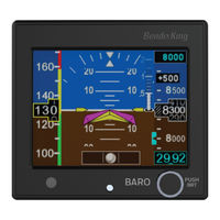
BENDIXKing KA 310 Pilot's Manual (48 pages)
Electronic Attitude Indicator and Autopilot Adapter
Brand:
BENDIXKing
| Category:
Avionics Display
| Size: 1 MB
Table of Contents
Table of Contents
9
1 System Overview
13
Introduction
13
KI 300 Product Description
13
Figure 1 KI 300 Electronic Attitude Indicator
13
KI 300 Functions
14
System Interfaces
16
KA 310 Product Description
17
Figure 2 KA 310 Autopilot Adapter
17
KA 310 Functions
18
Autopilot Interfaces
19
System Interfaces
19
2 Normal Operation
21
Initial Power on
21
Thermal Stabilization
21
Figure 3 Power on Screen
21
Figure 4 Heating Message
21
Alignment
22
Figure 5 Sensor & Battery Stabilization
22
Figure 6 Aligning Message
22
Pilot Display and Controls
23
Figure 7 Pilot Display & Controls
23
Indicated Airspeed
24
Figure 8 Pushbutton Controls
24
Figure 10 over and under Speed Indications
25
Figure 9 IAS Limits
25
Indicated Airspeed Limits
25
Over and under Speed Indications
25
Barometric Altitude
26
Baro Adjustment
26
Default Baro
26
Instantaneous Vertical Speed Indication (IVSI)
27
Figure 11 Climbing and Descending IVSI
27
Altitude Bug
28
Figure 12 Altitude Bug Modes (A) Disabled, (B) Adjusting/Editing, (C)
28
Roll & Pitch
29
Slip Indication
29
Figure 13 Example of Detached Horizon Line
29
Decision Height
30
Flight Director Command Bars
30
Figure 14 Slip Indicator Ball / Polygon
30
Figure 15 Decision Height Indicator
30
Figure 16 Flight Director Command Bars
30
Brightness Adjustment
31
Figure 17 Backlight Adjust Menu
31
3 Abnormal Operation
32
Warning Annunciations
32
Sensor Failure
32
Figure 18 Abnormal Operation Indicators
32
Figure 19 Red X'ed Indicators
32
Memory Error
33
Autopilot Output Fail Annunciation
33
Figure 20 Memory Error Message
33
Figure 21 Autopilot Output Fail Message
33
Data Output Fail Annunciation
34
Caution Annunciations
34
Degraded Attitude
34
Figure 22 Data Output Fail Warning Message
34
Attitude Re-Alignment
35
Data Output Fail Annunciation
35
Figure 23 Cross Check Message
35
Transition to and from Battery
36
Battery Status
37
Battery Duration
38
Cold Temperature Startup
39
Flight Director
40
Decision Height
40
Emergency Shutdown Procedure
40
4 Operational Limitations
42
Acronyms and Abbreviations
45
Advertisement
Related Products
BENDIXKing KSN 8 Series
BENDIXKing KSN 780
BENDIXKing KSN 900
BENDIXKing KSD 100EXP
BENDIXKing KG 71EXP
BENDIXKing KMG 7010
BENDIXKing KTP 73
BENDIXKing KAP 140
BENDIXKing KX 99
BENDIXKing KY 96A
BENDIXKing Categories
GPS
Transceiver
Avionics Display
Autopilot System
Monitor
More BENDIXKing Manuals
Login
Sign In
OR
Sign in with Facebook
Sign in with Google
Upload manual
Upload from disk
Upload from URL