Ambu aView 2 Advance Reference Manual
Hide thumbs
Also See for aView 2 Advance:
- Instructions for use manual (440 pages) ,
- Quick start manual (2 pages) ,
- Instructions for use manual (49 pages)

Related Manuals for Ambu aView 2 Advance


Summary of Contents for Ambu aView 2 Advance
- Page 1 Reference Manual for Ambu® aView™ 2 Advance For use by trained clinicians/physicians, qualified technicians and qualified professionals only. For in-hospital use. For use with Ambu® visualization devices.
- Page 2 Ambu is a registered trademark and aScope and aView are trademarks of Ambu A/S.
-
Page 3: Table Of Contents
3.7. Battery status on the graphical user interface ........................... 8 3.8. Connecting an Ambu visualization device ............................8 3.9. Connecting to external screens using HDMI or SDI ........................9 3.10. Connecting to Wi-Fi and local area network (LAN) ......................... 9 3.11. -
Page 4: Important Information
In this reference manual, the term displaying unit refers to aView 2 Advance. Please be aware that this manual does not explain or discuss clinical procedures. The reference manual describes only information and functions related to the operation of the aView 2 Advance. -
Page 5: Setting Up The Displaying Unit
3. Setting up the displaying unit This section explains the physical setup of the displaying unit in its place of operation. 3.1. Turning power ON and OFF Turn the displaying unit ON: Press the power button • on the side of the displaying unit. •... -
Page 6: Placing The Displaying Unit On A Solid Surface
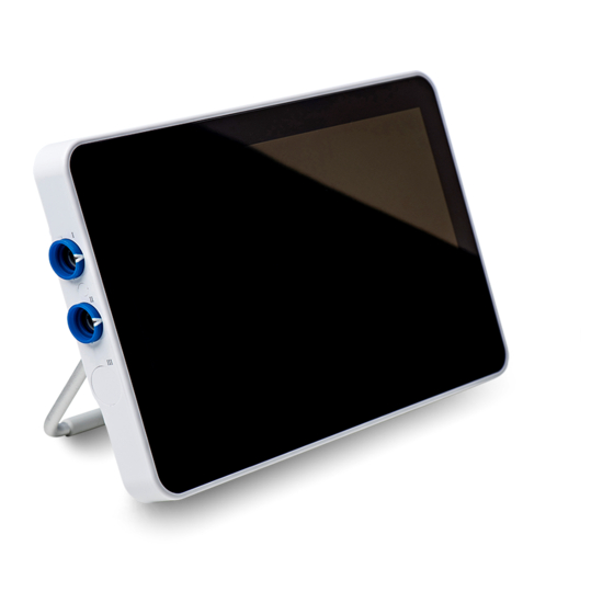
3.3. Placing the displaying unit on a solid surface Place the displaying unit on a solid flat surface by folding out the stand on the back of the displaying unit. The stand has multiple settings and can be adjusted to a suitable angle. -
Page 7: Power Button Light Indications
Unmounting the displaying unit from the bracket: • Use two hands to hold the displaying unit, while pressing the two grey release buttons on the bracket behind the displaying unit. • Pull the displaying unit towards yourself. 3.5. Power button light indications Green Light Orange Light Flashing orange... -
Page 8: Battery Status On The Graphical User Interface
The battery status is also indicated by the Battery level < 20% light in the power button. See section 3.5. 3.8. Connecting an Ambu visualization device The displaying unit has two identical connector ports for Ambu visualization devices marked with blue rings. -
Page 9: Connecting To External Screens Using Hdmi Or Sdi
3.9. Connecting to external screens using HDMI or SDI The graphical user interface and live image can be displayed on external screens in high-quality. An external screen can be connected using the HDMI or 3G-SDI video HDMI output ports located in the back of the displaying unit. -
Page 10: Setting Up The Displaying Unit Software
4. Setting up the displaying unit software Under the Settings tab, you will find all the menu related to setup of the displaying unit and connectivity. Here you will find the menus: Setup, User Profiles and About. In the Setup, menu all system settings, such as system language, date & time and network setup can be selected. In the User Profiles menu, you can create or edit user profiles (see section 4.3) . -
Page 11: System Setup
Monitoring and audit of the Ambu Imaging System • Complete data erase at disposal of the displaying unit A complete Ambu Imaging System is configured as illustrated in the figure below. The various connections are described in more detail in the following sections. -
Page 12: System Language
Ambu Imaging System Hospital Ambu Displaying Unit HDMI Visualization Device External screen Image and Video Streams Recordings /Log FIles USB 3.0 USB 3.0 Software Upgrade PACS Server DICOM Wi-Fi 4.2.1. System language In Language under the Setup menu the language preference for the graphical user interface is selected. By default, the language setting of the displaying unit is English. -
Page 13: Date And Time
4.2.2. Date and Time In Date & Time under the Setup menu the local date and time, where the displaying unit is used, can be selected. Press the Settings • tab in the tool bar on the right Press Setup and press Date & Time •... - Page 14 Setup Wi-Fi: Press the Settings • tab in the tool bar on the right Press Setup and press Network setup • See technical details about the configuration of Wi-Fi in Appendix 3. Open the Wi-Fi Regulatory Domain • drop-down menu and select your region from the list. •...
- Page 15 Connecting to a new network : Choose a new network from the list Available networks • Type the password for the selected network, press OK and press Connect. IP-address will be assigned automatically. • NOTE: Wi-Fi networks which require redirection to a login webpage for entering user name and password are not supported on the displaying units.
-
Page 16: Pacs Setup
Disconnecting from network: Press the connected network and then press the Disconnect button. 4.2.4. PACS setup In DICOM Setup under the Setup menu, you can configure connection to a PACS (picture archiving and communication system) to be able to transfer recorded images and video in DICOM (Digital Imaging and Communications in Medicine) format over the Wi-Fi or LAN network. - Page 17 Set up connection to PACS server: Press Add new, and the Configure new PACS server menu will appear. • • Press the first field (PACS name) and type to add the details Use the arrow > • to go to the next field...
-
Page 18: General Settings
The table below shows the information that must be filled out. Please contact your hospital IT and/or department PACS manager if you do not have this information available. Information needed Explanation PACS name This is the name of the PACS. Used in the export menu to select the PACS when transferring images and videos. -
Page 19: User Profiles
4.3. User profiles In the User Profiles menu, you can create new or edit existing user profiles. To access this menu, you must be logged in as Administrator. See sections below for login and information on user account privileges. 4.3.1. User types There are four types of users in the displaying unit: Default user, Advanced user (blue), the Administrator (orange) and the Service user (green). -
Page 20: Create And Edit User Profiles
Advanced User profile gives daily users the privileges to access the Archive and to export recorded files to PACS via DICOM. It is recommended to create at least one Advanced user profile (e.g. department login), or individual Advanced user profiles for each user of the displaying unit. It is not possible to create additional Administrator and Service User profiles. -
Page 21: Password Requirement
• Type a new name and/or select a new password and repeating the new password Press the Save • button Press OK in the pop-up window to confirm the change. • 4.3.3. Password requirement Passwords are required to be at least 8 characters. Any character is allowed. It is recommended to use a combination of capital and small letter, numbers and symbols to enhance password protection. -
Page 22: Operating The Displaying Unit
This section describes the functions in the user interface of the displaying unit. It is a prerequisite that the system is turned ON and an Ambu visualization device is connected to one of the two connector ports, as described in section 3.1 and section 3.8 respectively. -
Page 23: Adjusting Live Image Appearance
The time stamp indicates the time left on the battery while using a Battery 1:45 visualization device. Current Procedure View videos and snapshots recorded in the current procedure. Adjust colour, contrast, sharpness, brightness, and image orientation Image Adjustments (180 degrees rotation). When one of the other tabs (Archive, Login or Settings) in the tool bar is activated a first level menu opens extending over the black area left of the live image area. - Page 24 NOTE: The displaying unit will store the changes to the settings for each type visualization device individually and use these when the same type of visualization device is connected. As an example, if the settings are changed for Ambu® aScope™ 4 Broncho Slim these apply to all other aScope 4 Broncho Slim endoscopes connected, but not to any other aScope 4 variants.
-
Page 25: Rotation Of Live Image 180 Degrees
5.1.2. Rotation of live image 180 degrees The live image in the Live View can be rotated 180 degrees. This function is found in the Image Adjustment menu. Factory default this function is disabled. It can be enabled under General settings (see section 4.2.5) To activate live image rotation: Open the Image Adjustment menu and press Image Rotation... -
Page 26: Recording Images And Videos
5.1.4. Access recorded images and videos in Current Procedure folder When an Ambu visualization device is connected to the displaying unit, a procedure folder, called Current Procedure is created. This folder is used to store recorded images and videos. The folder is unique to the specific visualization device on the specific displaying unit, and the same folder is used if the visualization device is unplugged and plugged in again. -
Page 27: Zoom
The Current Procedure folder is now shown in the left side to the screen. The list of saved items shows the Procedure name and the Time at which the visualization device was first connected. The number on the Current Procedure folder icon show how many recordings have be made in the procedure. -
Page 28: Dual View
Zoom is active, the image will return to normal size. 5.1.6. Dual View The displaying unit can show two live images simultaneously when two Ambu visualizations devices are connected in at the same time (see section 3.8). -
Page 29: Archive
When two Ambu visualization devices are connected, only the Image Switch button, the Snapshot button or Video Recording button are available. Press the Image Switch button to swap the locations ans size of the live images from the two visualization devices. - Page 30 The Search field can be used to find specific procedures. Press the field and type a procedure date or words from a note added to a specific procedure. You can also choose to filter the procedure list to only see procedures in a given date range. Use the Select range •...
-
Page 31: Viewing Procedure Folder In Archive
5.2.1. Viewing Procedure Folder in Archive In the Procedure folder an overview of all recordings and information from the specific procedure is shown. To access, press a Procedure folder in the procedure list in the Archive • to view its content. 0:00:07 In the left side of the screen the Procedure name and a Notes... -
Page 32: Viewing Recordings
5.2.3. Viewing recordings To view a recorded image or video, press the recording you would like to view. Now the recording will be shown in full size. Below the full-size image, all recordings from the procedure are shown in descending order with the newest to the left. Scroll sideways on the thumbnails to see all recordings from the procedure. -
Page 33: Deleting Files
0:00:02 NOTE: It is not possible to take screenshots from a recorded video. Please use the snapshot feature in the Live View during the procedure for taking still images. 5.2.4. Deleting files You can delete recorded images and videos in a procedure folder. To delete files in the Procedure Folder overview: Use Selection box... -
Page 34: Export To Usb Or Pacs
5.2.5. Export to USB or PACS Images and videos recorded on the displaying unit can be exported to connected USB storage devices or to a PACS (Picture Archiving and Communication System – see section 4.2.4 for setup). The recordings can be exported in two formats: DICOM (Digital Imaging and Communications in Medicine) format and standard format called BASIC. -
Page 35: System Information And Upgrade
To export in DICOM format to a PACS or USB (for manual transfer to PACS): Press on DICOM (if view not selected already) • • Enter patient information All fields must be filled out. Choose the first field, fill it out, and use the arrows > to go to the next field. Patient ID (e.g. -
Page 36: System Upgrade
6.2. System upgrade In System Upgrade under the About the system upgrade function is placed. The software can only be upgraded by Ambu. For more information contact your local Ambu representative. -
Page 37: Reporting A Problem
6.3. Reporting a Problem In case you are experiencing problems with the displaying unit, please follow the troubleshooting guidelines in the IFU to find a solution. If this does not help you, please contact your local Ambu representative. 6.3.1. Export Log Files Log files can be exported from the displaying unit. -
Page 38: Appendix 1. Electromagnetic Compatibility
Appendix 1. Electromagnetic Compatibility Like other electrical medical equipment, the system requires special precautions to ensure electromagnetic compatibility with other electrical medical devices. To ensure electromagnetic compatibility (EMC) the system must be installed and operated according to the EMC information provided in this manual. The system has been designed and tested to comply with IEC 60601-1-2 requirements for EMC with other devices. - Page 39 Guidance and manufacturer’s declaration – electromagnetic immunity The system is intended for use in the electromagnetic environment specified below. The customer or the user of the system should assure that it is used in such an environment. Immunity test IEC 60601-1 Compliance Level Electromagnetic Environment Guidance test level...
- Page 40 Guidance and manufacturer’s declaration – electromagnetic immunity The system is intended for use in the electromagnetic environment specified below. The customer or the user of the system should assure that it is used in such an environment. Immunity test IEC 60601 test Compliance Electromagnetic Environment Guidance level...
-
Page 41: Appendix 2. Radio Frequency Compliance
Recommended Separation Distances Between Portable and Mobile RF Communication Equipment and system. The system is intended for use in an electromagnetic environment in which radiated RF disturbances are controlled. The user of the system can help prevent electromagnetic interference by maintaining a minimum distance between portable and mobile RF communications equipment (transmitters and the system as recommended below, according to the maximum output power of the communication equipment. - Page 42 Industry Canada statement (IC) EN: This device complies with ISED’s licence-exempt RSSs. Operation is subject to the following two conditions: (1) This device may not cause harmful interference, and (2) this device must accept any interference received, including interference that may cause undesired operation. FR: Le présent appareil est conforme aux CNR d’...
- Page 43 FCC Caution: Any changes or modifications not expressly approved by the party responsible for compliance could void the user's authority to operate this equipment. This transmitter must not be co-located or operating in conjunction with any other antenna or transmitter. This device meets all the other requirements specified in Part 15E, Section 15.407 of the FCC Rules.
-
Page 44: Appendix 3. Cybersecurity
• No PHI is stored in the displaying unit. • The displaying unit does not allow any input from external devices (except from Ambu visualization devices and secured software updates). • Essential functionality is secured in case of network problems. - Page 45 The log files exported are mainly for troubleshooting purposes by Application log Ambu staff, in case you encounter problems with the displaying unit. The files are compressed in a format more secure than Windows standard compression function. Unzipping the data requires a third...
- Page 46 3.22 Main database. None Many known issues, but none of these are critical to the Linux Linux The embedded Linux Displaying Unit. Kernel kernel is built custom Some of the media and interactions kernel are version by Ambu. described below.
- Page 47 Title Version Used for Known vulnerabilities from NVD (CVSS score) GStreamer 1.14.4 The following plugins CVE-2019-9928 (8.8) are used: Allows a heap-based buffer overflow in the RTSP connection v4l2src parser to potentially allow remote code execution. The displaying unit does not depend directly on RTSP input. It is only glupload used inside the board from EEPROM encoded Embedded Controller.
- Page 48 Ambu A/S Baltorpbakken 13 DK-2750 Ballerup Denmark T +45 72 25 20 00 F +45 72 25 20 50 ambu.com...
Need help?
Do you have a question about the aView 2 Advance and is the answer not in the manual?
Questions and answers