Sony Ericsson T650 Working Instruction, Mechanical
Hide thumbs
Also See for T650:
- White paper (53 pages) ,
- Troubleshooting manual, mechanical (28 pages) ,
- User manual (86 pages)
Table of Contents
Advertisement
Quick Links
Working Instruction, Mechanical
Applicable for T650 and T658
CONTENTS
1 Introduction .............................................................................. 3
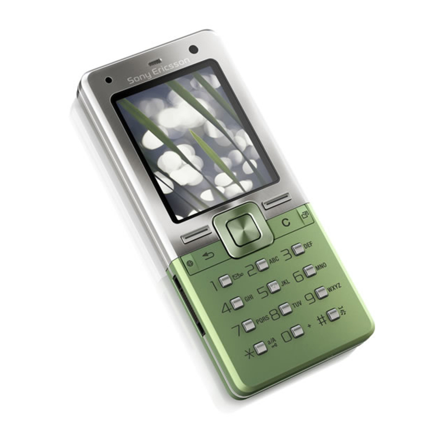
1.1 T650 ........................................................................................3
1.2 Equipment.................................................................................4
1.3 General cautions ......................................................................5
2 Disassembly ............................................................................. 6
2.1 Overview ...................................................................................7
3 Replacements......................................................................... 21
3.1 Cover rear Assembly .............................................................22
3.2 Battery .....................................................................................22
3.3 Keyboard Universal Generic .................................................22
3.4 Navigation keypad..................................................................22
3.5 Frame Assembly.....................................................................22
3.6 Keyfoil complete.....................................................................22
3.7 Loudspeaker ...........................................................................22
3.8 Holder M2 and SIM assy ........................................................23
3.9 Display.....................................................................................23
3.10 System Connector..................................................................24
3.12 Camera 3Mpixel ......................................................................26
3.13 Camera 3Mpixel continued....................................................27
3.15 Camera Key.............................................................................30
3.16 Ear Speaker.............................................................................31
3.17 Cover front keyplate...............................................................32
3.18 Volume Key.............................................................................34
3.19 On/Off Key...............................................................................35
3.20 Liquid Indicator ......................................................................36
3.21 KRH Label ...............................................................................37
3/000 21-1/FEA 209 544/118 A
©
Company Internal
Sony Ericsson Mobile Communications AB
2.1.1
Cover rear Assembly & Battery ............................................. 8
2.1.2
Front Cover ......................................................................... 10
2.1.3
Keyboard Universal Numeric............................................... 11
2.1.4
Navigation keypad............................................................... 12
2.1.5
Frame assembly.................................................................. 13
2.1.6
Keyfoil complete .................................................................. 14
2.1.7
Loudspeaker ....................................................................... 16
2.1.8
Holder M2 and SIM assy ..................................................... 17
2.1.9
Display & PBA ..................................................................... 19
Working Instruction, Mechanical
......................................................28
Advertisement
Table of Contents

Related Manuals for Sony Ericsson T650


Summary of Contents for Sony Ericsson T650
-
Page 1: Table Of Contents
Working Instruction, Mechanical Working Instruction, Mechanical Applicable for T650 and T658 CONTENTS 1 Introduction ................3 1.1 T650 ..................3 1.2 Equipment.................4 1.3 General cautions ..............5 2 Disassembly ................6 2.1 Overview ...................7 2.1.1 Cover rear Assembly & Battery ..........8 2.1.2... - Page 2 Navigation keypad............... 46 4.1.7 Keyboard Universal Numeric..........47 4.1.8 Front Cover ................. 48 4.1.9 Battery & Cover rear Assembly ........... 49 5 Revision history ..............50 3/000 21-1/FEA 209 544/118 A 2(50) © Company Internal Sony Ericsson Mobile Communications AB...
-
Page 3: Introduction
Working Instruction, Mechanical 1 Introduction 1.1 T650 3/000 21-1/FEA 209 544/118 A 3(50) © Company Internal Sony Ericsson Mobile Communications AB... -
Page 4: Equipment
• Hot air flow solder station • Zebra printer connected to computer OTHER EQUIPMENT • ESD-wristband • ESD-gloves • Isopropyl alcohol • Air blower 3/000 21-1/FEA 209 544/118 A 4(50) © Company Internal Sony Ericsson Mobile Communications AB... -
Page 5: General Cautions
REMEMBER TO REMOVE THE PROTECTION FOILS ON NEW PARTS SUCH AS THE LCD • NEVER TOUCH THE DISPLAY GLASS • USE AIR BLOW EQUIPMENT TO KEEP THE FRONT WINDOW AND DISPLAY MODULE DUST FREE 3/000 21-1/FEA 209 544/118 A 5(50) © Company Internal Sony Ericsson Mobile Communications AB... -
Page 6: Disassembly
Replacements for the actual replacement. REPLACEMENTS Contents Start page REASSEMBLY DISASSEMBLY Done 3/000 21-1/FEA 209 544/118 A 6(50) © Company Internal Sony Ericsson Mobile Communications AB... -
Page 7: Overview
3. Keyboard Universal Numeric 4. Navigation Keypad 5. Frame Assembly 6. Keyfoil complete 7. Loudspeaker 8. Holder M2 and SIM assy 9. Display (a) & PBA (b) 3/000 21-1/FEA 209 544/118 A 7(50) © Company Internal Sony Ericsson Mobile Communications AB... -
Page 8: Cover Rear Assembly & Battery
2.1.1 Cover rear Assembly & Battery Release the Battery Cover. Lift up the battery cover. Remove the Battery Cover. Grab the Battery and pull it up. 3/000 21-1/FEA 209 544/118 A 8(50) © Company Internal Sony Ericsson Mobile Communications AB... - Page 9 Working Instruction, Mechanical Cover rear Assembly & Battery continued Remove the Battery. 3/000 21-1/FEA 209 544/118 A 9(50) © Company Internal Sony Ericsson Mobile Communications AB...
-
Page 10: Front Cover
Start on the opposite side and do the same thing to release the Front cover from the Frame assembly. Use your fingers and wiggle the Front Cover upwards to release it from the Frame assembly. 3/000 21-1/FEA 209 544/118 A 10(50) © Company Internal Sony Ericsson Mobile Communications AB... -
Page 11: Keyboard Universal Numeric
Working Instruction, Mechanical 2.1.3 Keyboard Universal Numeric Remove the Keyboard Universal Numeric with your fingers. 3/000 21-1/FEA 209 544/118 A 11(50) © Company Internal Sony Ericsson Mobile Communications AB... -
Page 12: Navigation Keypad
Working Instruction, Mechanical 2.1.4 Navigation keypad Remove the Navigation keypad with your fingers. 3/000 21-1/FEA 209 544/118 A 12(50) © Company Internal Sony Ericsson Mobile Communications AB... -
Page 13: Frame Assembly
Use JCIS to remove the screw. Use the front opening tool to loose the Core Unit from the Frame. Gently remove the Core Unit from the Frame assembly. 3/000 21-1/FEA 209 544/118 A 13(50) © Company Internal Sony Ericsson Mobile Communications AB... -
Page 14: Keyfoil Complete
Lift up the Keyfoil complete against the Display. Use a front opening tool and pull it upwards to disconnect the Keyfoil complete from the BtB connector. 3/000 21-1/FEA 209 544/118 A 14(50) © Company Internal Sony Ericsson Mobile Communications AB... - Page 15 Working Instruction, Mechanical Keyfoil complete continued Remove the Keyfoil complete with your fingers. 3/000 21-1/FEA 209 544/118 A 15(50) © Company Internal Sony Ericsson Mobile Communications AB...
-
Page 16: Loudspeaker
Working Instruction, Mechanical 2.1.7 Loudspeaker Lift up this part of the Loudspeaker. Use the front opening tool to release the latch indicated. Remove the Loudspeaker with your fingers. 3/000 21-1/FEA 209 544/118 A 16(50) © Company Internal Sony Ericsson Mobile Communications AB... -
Page 17: Holder M2 And Sim Assy
Working Instruction, Mechanical 2.1.8 Holder M2 and SIM assy Use the front opening tool to release the latch indicated. Lift up the Holder against the System connector 3/000 21-1/FEA 209 544/118 A 17(50) © Company Internal Sony Ericsson Mobile Communications AB... - Page 18 Holder M2 and SIM assy continued Use a front opening tool and pull it upwards to disconnect the Holder from the BtB connector. Remove the Holder from the PBA. 3/000 21-1/FEA 209 544/118 A 18(50) © Company Internal Sony Ericsson Mobile Communications AB...
-
Page 19: Display & Pba
2.1.9 Display & PBA Use JCIS to remove the two screws. Use the front opening tool to release the latch indicated. Lift up the Display to the right. 3/000 21-1/FEA 209 544/118 A 19(50) © Company Internal Sony Ericsson Mobile Communications AB... - Page 20 Display & PBA continued Use a front opening tool and pull it upwards to disconnect the Display from the BtB connector. Remove the Display from the PBA. 3/000 21-1/FEA 209 544/118 A 20(50) © Company Internal Sony Ericsson Mobile Communications AB...
-
Page 21: Replacements
The instruction usually ends by directing you to the Reassembly section with a specification of the instructions you have to carry out in order to reassemble the phone. REPLACEMENTS Contents Start page DISASSEMBLY REASSEMBLY Done 3/000 21-1/FEA 209 544/118 A 21(50) © Company Internal Sony Ericsson Mobile Communications AB... -
Page 22: Cover Rear Assembly
Follow the 4.1.4 – 4.1.9 Reassembly instructions! 3.7 Loudspeaker Follow the 2.1.1 – 2.1.7 Disassembly instructions! Prepare the new Loudspeaker. Follow the 4.1.3 – 4.1.9 Reassembly instructions! 3/000 21-1/FEA 209 544/118 A 22(50) © Company Internal Sony Ericsson Mobile Communications AB... -
Page 23: Holder M2 And Sim Assy
Follow the 4.1.2 – 4.1.9 Reassembly instructions! 3.9 Display Follow the 2.1.1 – 2.1.9 Disassembly instructions! Prepare the new Display. Follow the 4.1.1 – 4.1.9 Reassembly instructions! 3/000 21-1/FEA 209 544/118 A 23(50) © Company Internal Sony Ericsson Mobile Communications AB... -
Page 24: System Connector
Follow the 2.1.1 – 2.1.8 Disassembly instructions! Use your fingers to remove the System Connector. INSTALLATION Use your fingers to position the System Connector. Follow the 4.1.2 – 4.1.9 Reassembly instructions! 3/000 21-1/FEA 209 544/118 A 24(50) © Company Internal Sony Ericsson Mobile Communications AB... -
Page 25: Camera Protection Lens & Camera Protection Lens Gasket
Use tweezers to assemble the Camera protection lens gasket on the Camera protection lens. INSTALLATION Use tweezers to position the Camera protection lens. Follow the 4.1.5 – 4.1.9 Reassembly instructions! 3/000 21-1/FEA 209 544/118 A 25(50) © Company Internal Sony Ericsson Mobile Communications AB... -
Page 26: Camera 3Mpixel
Push the 3Mpixel camera tool to bottom and wiggle the tool side to side before lifting the tool up. Use tweezers to remove the 3Mpixel camera 3/000 21-1/FEA 209 544/118 A 26(50) © Company Internal Sony Ericsson Mobile Communications AB... -
Page 27: Camera 3Mpixel Continued
Press gently on the top of the Camera 3Mpixel until it snaps into place. AUTION O NOT TOCH THE LENS Follow the 4.1.5 – 4.1.9 Reassembly instructions! 3/000 21-1/FEA 209 544/118 A 27(50) © Company Internal Sony Ericsson Mobile Communications AB... -
Page 28: Vga Camera - Only T650
Use tweezers to remove the VGA camera INSTALLATION Notice the small slot in the socket and the small slot in the VGA camera. 3/000 21-1/FEA 209 544/118 A 28(50) © Company Internal Sony Ericsson Mobile Communications AB... - Page 29 Use tweezers to position the VGA camera Press gently on the top of the VGA camera until it snaps into place. Follow the 4.1.1 – 4.1.9 Reassembly instructions! 3/000 21-1/FEA 209 544/118 A 29(50) © Company Internal Sony Ericsson Mobile Communications AB...
-
Page 30: Camera Key
Follow the 2.1.1 – 2.1.2 Disassembly instructions! Use tweezers to remove the Camera key. INSTALL Use tweezers to position the Camera key. Follow the 4.1.8 – 4.1.9 Reassembly instructions! 3/000 21-1/FEA 209 544/118 A 30(50) © Company Internal Sony Ericsson Mobile Communications AB... -
Page 31: Ear Speaker
O NOT TOUCH THE EAR SPEAKER SPRINGS Use a front opening tool to press the Ear speaker into its cavity. Follow the 4.1.1 – 4.1.9 Reassembly instructions! 3/000 21-1/FEA 209 544/118 A 31(50) © Company Internal Sony Ericsson Mobile Communications AB... -
Page 32: Cover Front Keyplate
Use your fingers and unsnap the Cover front keyplate from the Cover front. INSTALLATION Note It is very important that you follow the instruction below Use your fingers and press for 10 seconds. 3/000 21-1/FEA 209 544/118 A 32(50) © Company Internal Sony Ericsson Mobile Communications AB... - Page 33 Use your fingers and press for 10 seconds. Use your fingers and press for 10 seconds. Use your fingers and press for 10 seconds. Follow the 4.1.8 – 4.1.9 Reassembly instructions! 3/000 21-1/FEA 209 544/118 A 33(50) © Company Internal Sony Ericsson Mobile Communications AB...
-
Page 34: Volume Key
Follow the 2.1.1 – 2.1.2 Disassembly instructions! Use tweezers to remove the Volume key. INSTALLATION Use tweezers to position the Volume key. Follow the 4.1.8 – 4.1.9 Reassembly instructions! 3/000 21-1/FEA 209 544/118 A 34(50) © Company Internal Sony Ericsson Mobile Communications AB... -
Page 35: On/Off Key
Follow the 2.1.1 – 2.1.2 Disassembly instructions! Use tweezers to remove the On/Off key. INSTALLATION Use tweezers to position the On/Off key. Follow the 4.1.8 – 4.1.9 Reassembly instructions! 3/000 21-1/FEA 209 544/118 A 35(50) © Company Internal Sony Ericsson Mobile Communications AB... -
Page 36: Liquid Indicator
Remove the activated Liquid Indicator with the dentist hook and the tweezers. INSTALLATION Attach the new Liquid Indicator with the tweezers and the dentist hook. Follow the 4.1.5 – 4.1.9 Reassembly instructions! 3/000 21-1/FEA 209 544/118 A 36(50) © Company Internal Sony Ericsson Mobile Communications AB... -
Page 37: Krh Label
• Take the new label and place it onto the frame as in the adjacent picture NE LABEL ONLY IS ALLOWED Follow the 4.1.9 Reassembly instructions! 3/000 21-1/FEA 209 544/118 A 37(50) © Company Internal Sony Ericsson Mobile Communications AB... -
Page 38: Plug (External Antenna)
Follow the 2.1.1 Disassembly instructions! REMOVAL Use a dentist hook to remove the Plug (External antenna). INSTALLATION Use tweezers to position the Plug (External antenna). Follow the 4.1.9 Reassembly instructions! 3/000 21-1/FEA 209 544/118 A 38(50) © Company Internal Sony Ericsson Mobile Communications AB... -
Page 39: Reassembly
Reassembly section with a specification of the instructions you have to carry out in order to reassemble the phone. REPLACEMENTS Contents Start page DISASSEMBLY REASSEMBLY Done 3/000 21-1/FEA 209 544/118 A 39(50) © Company Internal Sony Ericsson Mobile Communications AB... -
Page 40: Overview
3. Loudspeaker 4. Keyfoil complete 5. Frame assembly 6. Navigation keypad 7. Keyboard Universal Numeric 8. Front Cover 9. Battery (a) & Cover rear assembly (b) 3/000 21-1/FEA 209 544/118 A 40(50) © Company Internal Sony Ericsson Mobile Communications AB... -
Page 41: Pba & Display
Plug the LCD flex film into the BtB connector on the PBA with your fingers. Fold down the Display over the PBA. Install two silver screws with torque screwdriver at 11 Ncm with a JCIS. 3/000 21-1/FEA 209 544/118 A 41(50) © Company Internal Sony Ericsson Mobile Communications AB... -
Page 42: Holder M2 And Sim Assy
Plug the Holder flex film into the BtB connector on the PBA with your fingers. Fold down the Holder over the PBA. Snap the latch of the Holder M2 and SIM assy. 3/000 21-1/FEA 209 544/118 A 42(50) © Company Internal Sony Ericsson Mobile Communications AB... -
Page 43: Loudspeaker
Working Instruction, Mechanical 4.1.3 Loudspeaker Position the Loudspeaker on the PBA with your fingers. Snap the latch of the Loudspeaker. 3/000 21-1/FEA 209 544/118 A 43(50) © Company Internal Sony Ericsson Mobile Communications AB... -
Page 44: Keyfoil Complete
Fold down the Keyfoil complete over the PBA. Snap the latch of the Key foil complete. Install one silver screw with torque screwdriver at 11 Ncm with a JCIS. 3/000 21-1/FEA 209 544/118 A 44(50) © Company Internal Sony Ericsson Mobile Communications AB... -
Page 45: Frame Assembly
Insert the PBA into the Frame assembly. Use your fingers to snap the PBA and Frame assembly together. Install one silver screw with torque screwdriver at 11 Ncm with a JCIS. 3/000 21-1/FEA 209 544/118 A 45(50) © Company Internal Sony Ericsson Mobile Communications AB... -
Page 46: Navigation Keypad
Working Instruction, Mechanical 4.1.6 Navigation keypad Use tweezers to position the Navigation keypad. 3/000 21-1/FEA 209 544/118 A 46(50) © Company Internal Sony Ericsson Mobile Communications AB... -
Page 47: Keyboard Universal Numeric
Working Instruction, Mechanical 4.1.7 Keyboard Universal Numeric Use tweezers to position the Keyboard Universal Numeric. 3/000 21-1/FEA 209 544/118 A 47(50) © Company Internal Sony Ericsson Mobile Communications AB... -
Page 48: Front Cover
Install four silver screws with torque screwdriver at 11 Ncm with a JCIS. Install four golden screws with torque screwdriver at 17 Ncm with a T6 bit. 3/000 21-1/FEA 209 544/118 A 48(50) © Company Internal Sony Ericsson Mobile Communications AB... -
Page 49: Battery & Cover Rear Assembly
Insert the contact end of the battery into the cavity. Press the battery down in the cavity. Position the battery cover with bottom first. Use your fingers to snap the Cover rear. 3/000 21-1/FEA 209 544/118 A 49(50) © Company Internal Sony Ericsson Mobile Communications AB... -
Page 50: Revision History
Working Instruction, Mechanical 5 Revision history Rev. Date Changes / Comments 2007-08-16 Initial release 3/000 21-1/FEA 209 544/118 A 50(50) © Company Internal Sony Ericsson Mobile Communications AB...
Need help?
Do you have a question about the T650 and is the answer not in the manual?
Questions and answers