
Related Manuals for Ametek Teseq TWT Series


Summary of Contents for Ametek Teseq TWT Series
- Page 1 TWT Amplifiers: QUICK-START GUIDE AND SAFETY INSTRUCTIONS Teseq TWT Series Version: 1.0 31.3.2021 Replaces: Filename: Quick Start and Saftey TWT Amplifier Series_1.1.docx Print date: 4.29.202121...
- Page 2 Sternenhofstrasse 15 4153 Reinach BL1 Switzerland Phone: +41 61 204 41 11 Fax: +41 61 204 41 00 URL : www.ametek-cts.com Copyright © 2021 AMETEK CTS GmbH All right reserved. Specifications subject to change. Quick Start and Safety Guide V 1.0...
-
Page 3: Table Of Contents
Table of Contents Table of Contents ..........................3 Safety ............................4 Safety Aspects ............................4 1.2. Safety symbols and terms .......................... 4 Safety Precaution ............................4 Installation ..........................7 General ............................... 7 Connecting the line cord..........................7 Connecting the chassis to a suitable ground connection................7 Connecting the RF cables .......................... -
Page 4: Safety
AMETEK CTS TWT Amplifiers Safety Safety Aspects The amplifier described in this manual is designed to be used only by qualified personnel. Installation and use of the amplifier in a manner not specified in this manual may impair the protection provided by the amplifier. Before use, inspect the amplifier for damage which may impair safety. - Page 5 AMETEK CTS TWT Amplifiers WARNING: Do not touch the inner conductor of the RF-output connector. High voltages can occur on the inner conductor of the RF output connector, or on cables or anten- nas connected to it. These can cause RF burns if touched.
- Page 6 AMETEK CTS TWT Amplifiers Use the safety interlock facility within danger areas. WARNING: Any area where personnel may come into direct contact with high power RF, or be exposed to non-ionising ra- diation, should be designated as a danger area. A barrier should be established around any such area, with a switch in place when the barrier is broken.
-
Page 7: Installation
AMETEK CTS TWT Amplifiers Installation General CAUTION! Exercise care when lifting. Amplifier models that are very heavy have a caution label on the top cover. Appropriate lifting practices should be observed during transportation, installation, or removal of the amplifier from its mounting position. When mounted in a rack, the amplifier must not be supported by the front panel fixing holes alone. -
Page 8: Connecting The Safety Interlock
AMETEK CTS TWT Amplifiers Use cable with the lowest loss that is practical. The connectors or wave guide should not be over-tightened, and any tightening instructions for the connector or wave guide should be observed. Ensure that any bends in ca- bles conform to the recommended minimum-bend-radius of those cables, especially where the cables enter the RF connectors. -
Page 9: Quick Start
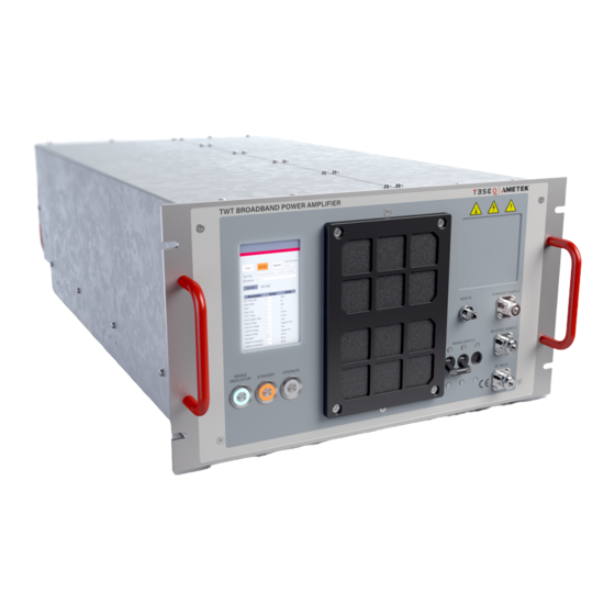
AMETEK CTS TWT Amplifiers Quick Start Rear Panel Connections A. Remote interface panel B. Mians power connector C. Earth/Ground Terminal D. Interlock Front Panel Connection & Control A. LCD Display B. AC Mains on indicator C. Standby (push button) D. Operate (push button) E. -
Page 10: Maintenance
Milmega and Teseq’ devices can be returned to AMETEK CTS in England or to their agency for adequate disposal. Alternatively, the equipment can be handed over to a specialized enterprise for disposal of electronic devices.
Need help?
Do you have a question about the Teseq TWT Series and is the answer not in the manual?
Questions and answers