Table of Contents
Advertisement
Quick Links
Advertisement
Chapters
Table of Contents
Troubleshooting

Subscribe to Our Youtube Channel
Related Manuals for Villa Sistemi Medicali Rotograph EVO 3D


Summary of Contents for Villa Sistemi Medicali Rotograph EVO 3D
- Page 1 Rotograph EVO 3D 0051 Service Manual Version 5 December 2011 (Rev. 1)
- Page 2 E831 description added in troubleshooting. from 10-77 to 10-83, Schematics and drawings update. 10-87, 10-89, Spare Parts update. from 11-11 to 11-13 (Ref. RDM 7454, RDM 7473, RDM 7474, RDM 7501, RDM 7502, RDM 7535, RDM 7578) (Rev. 1) Rotograph EVO 3D...
- Page 3 SERVICE MANUAL Revision history THIS PAGE IS INTENTIONALLY LEFT BLANK Rotograph EVO 3D (Rev. 1)
-
Page 4: Table Of Contents
Contents INTRODUCTION 1.1. Description of the system ..............1-2 1.2. Icons appearing in the manual ............1-3 1.3. How to contact VILLA SISTEMI MEDICALI technical service ....1-3 SAFETY INFORMATION 2.1. Warnings ..................... 2-2 2.1.1. Distribution of stray radiation ............2-5 2.1.2. - Page 5 6.7. Final checks ..................6-15 6.7.1. PC set up ..................6-15 6.7.1.1. PC – USB protection keys..........6-15 6.7.1.2. PC - Rotograph EVO 3D communication ......6-15 6.7.1.3. DICOM set-up ..............6-16 6.7.1.4. Image treatment filters setup .......... 6-17 6.7.2.
- Page 6 7.2.5.10. E775: RX button released during the emission ....7-25 7.2.6. Errors with code E800 and E801 ............ 7-26 7.2.6.1. E800: Timeout on CAN activation for vertical motor ..7-26 7.2.6.2. E801: ON/OFF command for vertical motor not changed on planned time ..........7-26 (Rev. 1) Rotograph EVO 3D...
- Page 7 7.3.6.2. Test input ports .............. 7-56 7.3.6.3. Pre-heating time ............. 7-58 7.3.6.4. Preheating level .............. 7-59 7.3.6.5. PAN RX emission / CEPH RX emission......7-60 7.3.7. System / Burn-in................7-61 7.3.8. Show configuration ................ 7-61 Rotograph EVO 3D (Rev. 1)
- Page 8 CEPH Sensor Calibration file installation ........9-16 9.5.5. Internal network set up ..............9-17 9.5.5.1. Direct point-to-point connection between PC and Rotograph EVO 3D............9-19 9.6. CEPH arm aligment ................9-20 9.6.1. Ear rings alignment................ 9-22 9.6.2. CEPH Sensor centering ..............9-27 9.6.3.
- Page 9 SERVICE MANUAL Contents THIS PAGE IS INTENTIONALLY LEFT BLANK Rotograph EVO 3D (Rev. 1)
-
Page 10: Introduction
Digital Acquisition System are given in the relevant Manuals, supplied with the Direct Digital Sensor. WARNING: 1. Rotograph EVO 3D is an electro-medical device and it can be used only under the supervision of a physician or of highly qualified personnel, with the necessary knowledge on X-ray protection. -
Page 11: Description Of The System
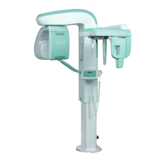
Rotograph EVO 3D, produced by VILLA SISTEMI MEDICALI S.p.A., is a complete panoramic system that allows the execution of all X-rays... -
Page 12: Icons Appearing In The Manual
This icon indicates a WARNING message; the items marked by this icon refer to the safety aspects of the patient and/or of the operator. 1.3. How to contact VILLA SISTEMI MEDICALI technical service For any technical queries please contact the following: •... - Page 13 SERVICE MANUAL Introduction THIS PAGE IS INTENTIONALLY LEFT BLANK Rotograph EVO 3D (Rev. 0)
-
Page 14: Safety Information
SAFETY INFORMATION WARNING: Please read this chapter thoroughly. Villa Sistemi Medicali designs and builds its devices complying with the related safety requirements; furthermore it supplies all information necessary for a correct use and the warnings related to danger associated with X-rays generating units. -
Page 15: Warnings
While performing the radiography, no-one, apart from the operator and the patient, must remain in the room. Rotograph EVO 3D has been built to support a continuous operation at intermittent load; therefore please follow the described use cycles to enable the device to cool down. - Page 16 SERVICE MANUAL Safety information Minimum distance from X-ray source 2 m Protected area Figure 2-1 - Panoramic version Minimum distance from X-ray source 2 m Protected area Figure 2-2 - Cephalometric version (Rev. 0) Rotograph EVO 3D...
- Page 17 3D and panoramic reconstruction PC via a shielded Ethernet cable "Cat.5e" or greater. Do not use this connector to connect the Rotograph Evo 3D to LAN networks. NOTE: The dimension of the "patient's environment" is defined as a distance of at least 1.5 m from the actual patient.
-
Page 18: Distribution Of Stray Radiation
"3D Dentition" examination mode and the following parameters set: 86 kV, 10 mA, 8 s. The distribution values in the table are expressed as air Kerma for mAs (µGy/mAs). (Rev. 0) Rotograph EVO 3D... -
Page 19: Electromagnetic Emissions
Safety information 2.1.2. Electromagnetic emissions In accordance with the IEC 60601-1-2 standard, the Rotograph EVO 3D is suitable for use in the specified electromagnetic environment. The purchaser or user of the system should assure that it is used in an electromagnetic environment as described below. -
Page 20: Electromagnetic Immunity
Safety information 2.1.3. Electromagnetic immunity In accordance with the IEC 60601-1-2 standard, the Rotograph EVO 3D is suitable for use in the specified electromagnetic environment. The purchaser or user of the system should assure that it is used in an electromagnetic environment as described below. - Page 21 Field strength for fixed RF transmitters, as determined by an electromagnetic site survey, should be less then the compliance level in each frequency range. Interference may occur in the vicinity of the equipment marked with the following symbol: Rotograph EVO 3D (Rev. 0)
-
Page 22: Recommended Separation Distances For Non-Life Supporting Equipment
2.1.4. Recommended separation distances for non-life supporting equipment Rotograph EVO 3D is intended for use in an electromagnetic environment in which radiated RF disturbances are controlled. The customer or the user of the system can help prevent electromagnetic interference by maintaining a minimum distance between portable and... -
Page 23: Environmental Risks And Displacement
• Column, rotating arm and extensions: iron, lead, aluminium, copper, glass-resin, and non-biodegradable plastic material. • Applied parts: non-biodegradable plastics, iron, aluminium. • Digital sensor: iron, lead, copper, integrated electronic components. Rotograph EVO 3D 2-10 (Rev. 0) -
Page 24: Symbols Used
SERVICE MANUAL Safety information 2.3. Symbols used In this manual and on the Rotograph EVO 3D itself, apart from the symbols indicated on the control panel, the following icons are also used: Symbols Description Device with type B applied parts... - Page 25 SERVICE MANUAL Safety information THIS PAGE IS INTENTIONALLY LEFT BLANK Rotograph EVO 3D (Rev. 0) 2-12...
-
Page 26: Description
SERVICE MANUAL Description DESCRIPTION 3.1. Identification labels and laser labels 6, 7 8 (*) (*) Only for 110-120V version (Rev. 1) Rotograph EVO 3D... -
Page 27: Identification Plates And Laser Labels "220-240V" Version
SERVICE MANUAL Description 3.1.1. Identification plates and laser labels "220-240V" version Rotograph EVO 3D data plate Tube-head characteristics plate EVO XP plate CEPHALOMETRIC device plate (Additional projection package) (N° 2) Spot Laser indicator plate PANCEPH digital sensor data plate (N° 2) Laser symbol... -
Page 28: Identification Plates And Laser Labels "110-120V" Version
SERVICE MANUAL Description 3.1.2. Identification plates and laser labels "110-120V" version Rotograph EVO 3D data plate Tube-head characteristics plate EVO XP plate CEPHALOMETRIC device plate (Additional projection package) PANCEPH digital sensor data plate (N° 2) Spot Laser indicator label (N° 2) Laser... -
Page 29: Function, Models And Version
SERVICE MANUAL Description 3.2. Function, Models and Version Rotograph EVO 3D, produced by VILLA SISTEMI MEDICALI S.p.A., is a complete panoramic system, which enables to perform all X-rays commonly necessary in dental field (except for endoral X-rays) and volumetric three-dimensional images. -
Page 30: Version With Cephalometric Device
The values of exposure factors given in the tables of paragraph 6.7.6.1, set as default, are guidelines. The real adjustment of these values depends on different conditions, such as the preference of the user for very/little exposed images. (Rev. 1) Rotograph EVO 3D... -
Page 31: Evo Xp (Extended Projection Package) - Optional
The UIC code can be displayed by pressing the "Right Arrow/Left Arrow" during the start-up phase. The UIC code is simply an identifier of the single Rotograph EVO 3D unit; in order to enable the optional functions it is necessary to request the activation code from Villa Sistemi Medicali, which derives from the Unique Identification Code or from the device serial number. -
Page 32: Block Diagram
Block diagram This paragraph provides a brief description, at block diagram level, of the Rotograph EVO 3D. Aim of this paragraph is to provide a brief description of the system. More details about the electronic circuits which compose the system can be obtained by analyzing the schematics provided in Chapter 10. -
Page 33: Power Supply Assembly
The power supply assembly module also includes the Column CPU board (A1) that is dedicated to the control of the vertical column motion during all phases (slow speed, ramp up to high speed, ramp down from high to low speed, end run microswitches control, etc.). Rotograph EVO 3D (Rev. 1) -
Page 34: Cpu Board (A5 And A6)
(LED H12) provided by the Power supply assembly and generating on board the requested voltages (+5V, +3.3V and +1.5V). Three LED's on the board indicate the presence of these 3 voltages (+5V=LED H2, +3.3V=LED H3, +1.5V=LED H5). (Rev. 1) Rotograph EVO 3D... -
Page 35: Cpu Board Jumper Configuration
XJ6 = 2-3 • XJ8 = 2-3 • XJ11 = Open if CEPH is present / Closed if CEPH is not present • XJ12 = Open • XJ13 = Closed XJ13 XJ12 XJ11 Figura 3-1 Rotograph EVO 3D 3-10 (Rev. 1) -
Page 36: Generator Board (A10) And Tubehead
Generator board and relevant Generator CPU. Possible anomalous conditions are then communicated to the main CPU board (A5) which in turn generates error codes to alert the operator. (Rev. 1) 3-11 Rotograph EVO 3D... -
Page 37: Keyboard (A4)
5 different options (English, Italian, French, German and Spanish). The language selection is only available for the messages dedicated to the user. The messages relative to the service programs (Password) are always in English. Rotograph EVO 3D 3-12 (Rev. 1) - Page 38 SERVICE MANUAL Description Figure 3-1 – Block diagram (Rev. 1) 3-13 Rotograph EVO 3D...
-
Page 39: Control Panel - Descriptions And Functions
3.4. Control panel - Descriptions and functions The Rotograph EVO 3D keyboard is divided into function areas, plus a display to view the operative messages and error signals. The next figure shows a general view of the keyboard, while details on each functional area are provided in the following pages. - Page 40 Standard three available LEDs. Retracted The arch selection does not influence the values of kV and mA but acts on the position of the focus layer. (Rev. 1) 3-15 Rotograph EVO 3D...
- Page 41 ON/OFF the laser centring devices that allow the correct positioning of the medial-sagittal and Frankfurt planes, by adapting Rotograph EVO 3D to the patient's anatomy. The key "Test" is used to avoid the X-rays emission, in order to check the absence of collisions with the patient.
-
Page 42: Key Functions Description
> Repositioning the rotation group (to bring the group to the initial position after the examination and to exit from the "making an exposure") mode > Confirmation (Rev. 1) 3-17 Rotograph EVO 3D... - Page 43 SERVICE MANUAL Description THIS PAGE IS INTENTIONALLY LEFT BLANK Rotograph EVO 3D 3-18 (Rev. 1)
-
Page 44: Technical Data
SERVICE MANUAL Technical data TECHNICAL DATA General features Device type Rotograph EVO 3D Manufacturer VILLA SISTEMI MEDICALI Buccinasco (MI) Italia Class Class II B for European Directive for Medical Devices 93/42 Class II for Canadian MDR Class I with type B applied parts... - Page 45 Left, TMJ Right, Sinus Cephalometry and Carpus • Normal resolution in Latero-Lateral or Antero- Posterior projections (different sizes) • High resolution in Latero-Lateral or Postero/Anterior projections (different sizes) • High resolution Carpus exams • Motorised soft tissue filter Rotograph EVO 3D (Rev. 1)
- Page 46 1: 1.10 geometric magnification 1 : 1 magnification after software correction (*) Tube-head characteristics Model MRE 05 Manufacturer Villa Sistemi Medicali S.p.A. 20090 Buccinasco (MI) Italia Maximum tube voltage 86 kV accuracy ± 8 % Maximum anodic current 12 mA Anodic current accuracy ±...
- Page 47 NOTE: The Rotograph EVO 3D version without cephalometric arm, uses only the wide range sensor both for 3D images as well as for Panoramic images (narrow beam), while is also used the second PANCEPH sensor in the version with Cephalometric arm.
- Page 48 Relative working humidity (RH) range 30% ÷ 75% Temperature range for transport and - 20° ÷ + 70° storing Humidity range for transport and < 95% without condense storing Minimum atmospheric pressure for 630 hPa transport and storing (Rev. 0) Rotograph EVO 3D...
-
Page 49: Separate Parts Supplied With Rotograph Evo 3D
SERVICE MANUAL Technical data 4.1. Separate parts supplied with Rotograph EVO 3D Rotograph EVO 3D comes with the following removable accessories: Temple clamp centring device for standardised and volumetric exams Chin rest for standard panoramic, supplied with removable appendix for... - Page 50 Some of these parts do not carry identification codes due to their small size. The use of these parts on other devices is not possible, since they are parts designed specifically for the Rotograph EVO 3D. (Rev. 0) Rotograph EVO 3D...
-
Page 51: Applied Safety Regulations
4.2. Applied safety regulations Rotograph EVO 3D complies with the following standards: 0051 Ensures the compliance of the Rotograph EVO 3D to the Medical Device Directive 93/42/EEC and its revised version for medical devices issued by the European Community. •... -
Page 52: Loading Curve Of The Tube And Cooling Curve Of The Anode
SERVICE MANUAL Technical data 4.3. Loading curve of the tube and cooling curve of the anode Tube "CEI - OPX / 105" (0.5 IEC 60336) Load Anode cooling curve (Rev. 0) Rotograph EVO 3D... - Page 53 SERVICE MANUAL Technical data Tube-head heating and cooling curve Rotograph EVO 3D 4-10 (Rev. 0)
-
Page 54: Measurement Method Of Technical Factors
Particularly, in accordance with IEC 60601-2-7, the maximum deviation (including the correction and instrument’s accuracy) is less than or equal to ±10 for kV, while for tube current is less than or equal to ± 15%. (Rev. 0) 4-11 Rotograph EVO 3D... -
Page 55: Dimensions
SERVICE MANUAL Technical data 4.5. Dimensions 1020 (40,16") Ø 1040 (40,95") Ø 1140 (44,88") with free standing base Figure 4-1 - Base version Rotograph EVO 3D 4-12 (Rev. 0) - Page 56 SERVICE MANUAL Technical data 1020 (40,16") Ø 1040 (40,95") Ø 1140 (44,88") with free standing base 1910 (75,20") 1970 (77,56") with free standing base Figure 4-2 - Version with cephalometric unit (Rev. 0) 4-13 Rotograph EVO 3D...
- Page 57 SERVICE MANUAL Technical data THIS PAGE IS INTENTIONALLY LEFT BLANK Rotograph EVO 3D 4-14 (Rev. 0)
-
Page 58: Pre-Installation
• minimum width of 80 cm (31.50"). WARNING: In its standard versions, Rotograph EVO 3D must be fixed to the wall with the two brackets supplied. Each dowel must support a max. extraction force of 120 kg (264 lbs). The fixing dowels to be employed, for any kind of wall, are the following: full or concrete bricks: screw anchors (provided with the •... -
Page 59: Electrical Setting Up
NOTE: The electrical connection must be done on the terminal board X0 (see operation circuit diagram – chapter 10). Rotograph EVO 3D (Rev. 1) - Page 60 SERVICE MANUAL Pre-installation NOTE: Rotograph EVO 3D, IS SET TO connect, at the entrance of the X-ray room, the following control and warning devices: REMOTE X-RAYS BUTTON: "Dead man switch" remote control, • enables to perform the exam at a distance, the operator can stand outside the X-ray emission area.
- Page 61 Power voltages for the relevant devices have to be provide from outside, making sure not to exceed the indicated ratings. To connect all control and warning devices it is advisable to set 6 wires with 0.5 mm² section minimum. Rotograph EVO 3D (Rev. 0)
-
Page 62: Packaging
SERVICE MANUAL Pre-installation 5.2. Packaging Rotograph EVO 3D in base version is delivered in two carton-board boxes; the device equipped with Cephalometric unit will be delivered in three boxes. Weight Contents Gross - Axis movement device, complete with 80 kg... -
Page 63: Space Requirements
SERVICE MANUAL Pre-installation 5.3. Space requirements 5.3.1. Version without CEPH (*) A = minimum 600 mm (23.6"), recommended 800 mm (31.5") for service purpose Figure 5-1 Rotograph EVO 3D (Rev. 0) -
Page 64: Version With Ceph
Version with CEPH A = 600 mm (23.6") minimum, 800 mm (31.5") recommended for service purpose (**) B = 1460 mm (57.52") minimum front space, 1610 mm (63.39") recommended front space for service purpose Figure 5-2 (Rev. 0) Rotograph EVO 3D... - Page 65 SERVICE MANUAL Pre-installation THIS PAGE IS INTENTIONALLY LEFT BLANK Rotograph EVO 3D (Rev. 0)
-
Page 66: Installation
Installation INSTALLATION NOTE: Rotograph EVO 3D is delivered pre-mounted in groups; it is contained in 2 (PAN version) or 3 boxes (CEPH version). The mechanical mounting consists exclusively in assembling the above mentioned groups. Most of the adjustment are carried out in factory. -
Page 67: Setting Of The Wall
This paragraph is valid only for wall mounted version. NOTE: Rotograph EVO 3D has been designed for a wall fixing by two brackets, each of which requires to be fixed by three dowels. In order to find the right position of the brackets, it is necessary to use the quotes indicated in the Figure 6-1. -
Page 68: Column Mounting
2. With the column in vertical position, remove only the two fixing brackets "A". NOTE: Leave the retaining bracket "B" in place, because it will be necessary for the following operations of support arm mounting. (Rev. 0) Rotograph EVO 3D... - Page 69 "F" (Figure 6-3) from the upper bracket "C". Rotate the column. NOTE: Rotograph EVO 3D is equipped with a switch (S2) which allows to move the column vertically for service use. It is located in the back lower side of the column, protected by a metallic cover.
- Page 70 SERVICE MANUAL Installation Upper fixing plates "E" Retaining bracket "B" Screws "F" Upper wall bracket "C" Spacers Lower fixing plate "D" Figure 6-3 (Rev. 0) Rotograph EVO 3D...
-
Page 71: Mounting Of The Rotating Arm Assembly
(Figure 6-4 - This operation requires the presence of two persons). Handling zones Handling zones Figure 6-4 3. Move the rotating arm near the column from lateral side in order to avoid contacts between the Digital Sensor holder and the chin support. Rotograph EVO 3D (Rev. 0) - Page 72 6. Insert the reference pins "B" (Figure 6-6) between the rotating arm and column using a hammer. Insert the remaining two screws "C" (Figure 6-6) and tighten all the fixing screws. Retaining bracket Figure 6-6 (Rev. 0) Rotograph EVO 3D...
- Page 73 9. Open the sensor holder and mount the rotating arm lower cover (Figure 6-8). NOTE: In case of Ceph up-gradable version or single sensor version, in order to mount the rotating arm lower cover, it is necessary to remove the sensor holder internal covers. Rotograph EVO 3D (Rev. 0)
- Page 74 SERVICE MANUAL Installation Figure 6-8 10. Mount the temple support group inserting and rotating it in the relevant shaft (Figure 6-9) until the group is locked. Temple support shaft Figure 6-9 (Rev. 0) Rotograph EVO 3D...
- Page 75 For 110-120V version, to access to the CPU board connectors, it is necessary to remove the metallic cover. At the end of the connections, position the cables in the relevant seating and remount the cover. Rotograph EVO 3D 6-10 (Rev. 1)
-
Page 76: Mounting Of Ceph-Arm (Optional)
The CEPH kit can be installed on the machine both during the first installation and later as updating of the device. In case the Rotograph EVO 3D is sold already equipped with the Ceph arm, centering between the X-ray beam and the Sensor will be very quick as the arm is already adjusted and pinned in the factory. - Page 77 5. Insert the cables in the hole between column and rotating arm and connect them to the relevant connectors on the CPU and Digital boards. 6. Remove the red handle. Reference pin Reference pin Figure 6-11 Rotograph EVO 3D 6-12 (Rev. 1)
-
Page 78: How To Mount The Coverings
"F" (Figure 6-3) from the upper bracket "C". Rotate the column in clockwise direction in order to reach the column back side. Figure 6-12 (Rev. 0) 6-13 Rotograph EVO 3D... -
Page 79: Inserting The Ceph Sensor In The Sensor Holder
The digital sensor can still function correctly also when the colour changes, displaying a fall that might also not have damaged the sensor. NOTE: The fall sensor colour change interrupts the warranty on the sensor. Rotograph EVO 3D 6-14 (Rev. 0) -
Page 80: Final Checks
LAN connection. The system is provided with an Ethernet cable in order to permit the PC connection. In case there is no communication between Rotograph EVO 3D and computer, it is necessary to check the parameters installed in PC and equipment following instruction in paragraph 9.5.5. -
Page 81: Dicom Set-Up
WARNING: Do not change the IP address of the network card used to communicate with the Rotograph EVO 3D (usually 192.168.2.xxx). In order to connect the PC in the Dicom network, it is necessary to use the second network card. -
Page 82: Image Treatment Filters Setup
To setup post processing filters, refer to paragraph 9 of Dental Studio User Manual. It is suggested to use "Sharpen maximum" and "Media standard" filters; for Ceph it is suggested to use "Sharpen medium" filter. (Rev. 0) 6-17 Rotograph EVO 3D... -
Page 83: Verification Of The Panoramic Function
1. Switch on the machine and go to Exam Selection. 2. Open a new patient used to make the test images. 3. Select the TAC icon to open the virtual keyboard and select Pan function. Figure 6-13 Rotograph EVO 3D 6-18 (Rev. 0) - Page 84 5. Make an exposure in Adult mode at 68kV – 6mA using the copper filter or 60kV - 6mA without the copper filter, acquired in the DentalStudio program; the following image will be displayed. Figure 6-16 (Rev. 0) 6-19 Rotograph EVO 3D...
- Page 85 8. Measure also the two half of the image in order to check symmetry. The difference has to be max. 1mm. If there is not symmetry on the image, it is necessary to adjust the rotation offset entering in password 118 (see paragraph 7.3.4.1). Rotograph EVO 3D 6-20 (Rev. 0)
-
Page 86: Image Verification For The 3D Function
4. The image has to provide a continuous line as shawn in the following Figure. Figure 6-18 5. In case the arc is not correct, it will be necessary to modify the lateral offset as described in the paragraph 9.2.2. (Rev. 0) 6-21 Rotograph EVO 3D... -
Page 87: Verification Of The Ceph Function
3. Verify that the rings are centered in the exposed area: − If the rings are not centered (Figure 6-19), it is necessary to adjust the mechanical position of the rings (see paragraph 9.6.1). Rotograph EVO 3D 6-22 (Rev. 1) - Page 88 If the image is not symmetric in the window (Figure 6-20), it will be necessary to adjust the CEPH sensor position (see paragraph 9.6.2). Figure 6-20 4. Select "CEPH sensor zero" menu (see paragraph 9.6.3) to check the secondary collimator position. (Rev. 1) 6-23 Rotograph EVO 3D...
- Page 89 6. Press key "Patient entrance" (7) . The primary and secondary collimators and the ceph sensor go to the ceph central position. Place the centering tool P/N 5209900900 on the secondary collimator. Figure 6-22 Centering tool P/N 5209900900 Rotograph EVO 3D 6-24 (Rev. 1)
- Page 90 8. Take X-ray pressing the X-ray button and check if in the obtained narrow image the projection of the slit of the centering tool is vertical and in the middle of the impressed area, which is defined by the arc identified in the figure. Figure 6-23 (Rev. 1) 6-25 Rotograph EVO 3D...
- Page 91 Soft Tissue Filter. 11. Press "Examination mode Selection – M" (11) key, this operation insert also the secondary collimator in field. 12. Make a exposure with the same parameters (60kV – 6mA – 0.5s). Figure 6-25 Rotograph EVO 3D 6-26 (Rev. 1)
- Page 92 13. Measure the distance between the center of the ear rings and the edge of the soft tissue filter. The value has to be around 50mm (considering that the measure scale is not 1:1). (Rev. 1) 6-27 Rotograph EVO 3D...
-
Page 93: Verification Of Exposure Parameters
When this message appears, press the column up and column down keys simultaneously and hold them pressed. After 3 seconds, the following message will be displayed E R V I M E N U C O N F G U R A T I Rotograph EVO 3D 6-28 (Rev. 0) - Page 94 To move to mA and exposure time, press key (3) once or twice again. In this situation, the increase key (4) and the decrease key (5) will change the parameter. Pressing the X-ray button will start the emission. (Rev. 0) 6-29 Rotograph EVO 3D...
- Page 95 WARNING: X-ray will be emitted during the performance of the following operations. Authorised technicians are therefore recommended to use the greatest caution and to comply with the safety regulations and laws of their country. Rotograph EVO 3D 6-30 (Rev. 0)
-
Page 96: 6.7.5.1.1. Kvp
The high voltage value must be within 8% of the set value, while the time value must be within 10% of the set value. If the voltage is not within the expected range, replace the tubehead; otherwise replace Generator CPU board. (Rev. 0) 6-31 Rotograph EVO 3D... -
Page 97: 6.7.5.1.2. Ma Check
Generator board (A10). The exposure time calculated at about 75% of the maximum kV value, must correspond to the set one +10%. In case the time is outside the prescribed values, replace the CPU. Rotograph EVO 3D 6-32 (Rev. 0) -
Page 98: Non-Invasive Method
This program allows you to carry out the measuring of the exposure parameters with the tube-head arm in a fixed position (not rotating) without variations due to spine compensation. 3. Place the measuring instrument. (Rev. 0) 6-33 Rotograph EVO 3D... - Page 99 6. To end the control program, press key "Test" (6) ; the display will indicate: A N O R A M I and the unit will return to standard mode. Rotograph EVO 3D 6-34 (Rev. 0)
-
Page 100: Storing Of Automatic Exposure Parameters
LEDs relating to the keys for patient and size (that are being modified) will light up. Press the key "Patient Entrance" (7) to confirm or the key "Test" to cancel the setting. (Rev. 0) 6-35 Rotograph EVO 3D... -
Page 101: Table Of Pre-Set Anatomic Parameters
Installation 6.7.6.1. Table of pre-set anatomic parameters PANORAMIC TMJ open/close mouth Adult Adult Child Child Small Small Medium Medium Large Large SINUS Adult Child Small Medium Large 3D Dentition Adult Child Small Medium Large Rotograph EVO 3D 6-36 (Rev. 0) - Page 102 3D TMJ Left / 3D TMJ Right Adult Child Small Medium Large 3D Sinus Adult Child Small Medium Large CEPHALOMETRY (L.L) CEPHALOMETRY (A/P - P/A) Adult Adult Child Child Small Small Medium Medium Large Large (Rev. 0) 6-37 Rotograph EVO 3D...
- Page 103 SERVICE MANUAL Installation THIS PAGE IS INTENTIONALLY LEFT BLANK Rotograph EVO 3D 6-38 (Rev. 0)
-
Page 104: Troubleshooting
Check the correct insertion of X53 and X57; if it is (ON during emission) correct, replace the tubehead, otherwise insert it correctly and make another exposure. Replace the tubehead if it will glow again. As per H5 above. (Rev. 0) Rotograph EVO 3D... -
Page 105: Cpu Board A5 Led
If all the LEDs are OFF, verify the column fuse F3; if it is OK, verify cable X11 between column CPU board A1 and CPU board A5, on both sides. Verify the column CPU board A1. Rotograph EVO 3D (Rev. 0) -
Page 106: Displayed Messages
SERVICE MANUAL Troubleshooting 7.2. Displayed messages Rotograph EVO 3D is fully driven by a microprocessor which controls the programming of the emission parameters and indicates via displayed messages the different conditions of the unit and any defects and errors that occur. - Page 107 Secondary collimator on Digital CEPH Code Error description Reference chapter Unexpected activation of optical sensor secondary 7.2.3.1 collimator Timeout on ceph secondary collimator 7.2.3.1 Secondary collimator micro never active 7.2.3.1 Secondary collimator micro always active 7.2.3.1 Rotograph EVO 3D (Rev. 0)
- Page 108 Code Error description Reference chapter Timeout of zero position optical sensor of STF 7.2.4.1 STF zero position sensor always active 7.2.4.1 Code Error description Reference chapter Wrong setting in PAN + CEPH system configuration 7.3.3.9 (Rev. 0) Rotograph EVO 3D...
- Page 109 SW versions are displayed Keyboard Code Error description Reference chapter More than one key pressed on Power on 7.2.8.1 Column up and/or Column down pressed on 7.2.8.2 power on Key RESET (patient centering) pressed during 7.2.8.3 movement Rotograph EVO 3D (Rev. 1)
-
Page 110: Errors With Code From E000 To E199
7.2.1.1. E108: Hardware key fault This error is shown when the firmware of the Rotograph EVO 3D does not sense the presence of the U.I.C. (Unique Identification Code). The unique code is read, with is check byte, from the control system at the start-up;... -
Page 111: Errors With Code From E200 To E299
2. If the arm moves, verify the cable up to the CPU board (A5). If it still continues to have no variation of the signals when there is an activation of the switches, change the CPU board. Rotograph EVO 3D (Rev. 0) -
Page 112: E205 Timeout On Rotation
CPU board (A5), connector X25/X25. 2. If the motor is running, check the optical sensor B2 and its cables to X60 of A7 up to connector X25/X26 of main CPU board (A5). Replace the sensor or the faulty cables. (Rev. 0) Rotograph EVO 3D... -
Page 113: E240: Zero Position Sensor For Y Axes Always Active / E241: Zero Position Sensor For Y Axes Never Active / E242: Unexpected Activation Of Y Axes / E243: Timeout Of Y Axes
In case of no motion, it is possible that the problem is related to the motor: in order to check this, connect the driver of the Y-axis motor to the rotation motor, putting cable X28 into connector X26 on CPU board (A5). Rotograph EVO 3D 7-10 (Rev. 0) -
Page 114: E280: Unexpected Activation Of Zero Position Sensor On
X1-2 of the board up to X23, X24 and X34 of the main CPU; check the continuity of the interested wires and replace the faulty one (if any). • If all cables are OK, the fault is on the CPU, so replace it. (Rev. 0) 7-11 Rotograph EVO 3D... -
Page 115: Errors With Code From E300 To E399
X1-2 of the board up to X23, X24 and X34 of the main CPU; check continuity of the interested wires and replace the faulty one (if any). • If all cables are OK, the fault is on the CPU, so replace it. Rotograph EVO 3D 7-12 (Rev. 0) -
Page 116: E320: Unexpected Activation Of Zero Position Sensor On
Power on the system and check the functioning of the sensor, measuring the DC voltage on the terminal of the sensor B8, with and without an obstacle manually inserted. A variation of about 3.5 V minimum should be observed. If not, replace the sensor. (Rev. 0) 7-13 Rotograph EVO 3D... - Page 117 X58 and from that connector to X31 of the main CPU A5; check continuity of the interested wires and replace the faulty one (if any). • If all cables are OK, the fault is on the CPU, so replace it. Rotograph EVO 3D 7-14 (Rev. 0)
-
Page 118: E340: Sensor Holder Not In Pan Position
If this does not reset the error message: • Check the proper function of optical sensor B6. • Check continuity of cables from optical sensor to A8 board, connector X48, and from that board to main CPU board (A5), connector X33. (Rev. 0) 7-15 Rotograph EVO 3D... -
Page 119: E360 And E361: X-Ray Button Pressed During Power On
Before accessing the Generator CPU and power board (A9 and A10), it is mandatory to switch off the mains and wait up to 2 minutes in order to allow the discharge of the capacitor. Rotograph EVO 3D 7-16 (Rev. 0) -
Page 120: E362: X-Ray Button Released During The Examination Procedure
This can be generated by a bad connection or by a fault of the local Generator CPU board (A9). Check the CANBus cable X20-X20 and replace it if faulty, otherwise replace the Generator CPU board or then the Generator board. (Rev. 0) 7-17 Rotograph EVO 3D... -
Page 121: E381: Timeout On Activating Can Protocol On Generator Board / E382: Hf Not Answering To Can Protocol
In both cases, the error can be generated by a bad connection of the CANBus or a fault on the local Generator CPU board or a foult on the Generator board, so the steps above described for E380 are applied. Rotograph EVO 3D 7-18 (Rev. 0) -
Page 122: Errors With Code From E400 To E499
B9 in X33 of the main CPU and the continuity of the connection. • If all cables are OK, the fault is on the CPU, so replace it. (Rev. 0) 7-19 Rotograph EVO 3D... -
Page 123: Errors With Code From E700 To E799
Before accessing the Generator CPU and power board (A9 and A10), it is mandatory to switch off the mains and wait up to 2 minutes in order to allow the discharge of the capacitor. Rotograph EVO 3D 7-20 (Rev. 0) -
Page 124: E750: No Power To The Generator Board
13.3k ± 2% while is 14.3k ± 2% between pins 4 and 3 of the same connector; if correct values are measured, replace before the tubehead and, eventually, the Generator board. If incorrect values are measured, replace the tubehead and then the Generator board. (Rev. 0) 7-21 Rotograph EVO 3D... -
Page 125: E752: Filament Overload / E753: Overload On Anodic Current
If the error is present in stand-by mode, replace the Generator board (A10). If the error appears during an exposure, reset the error and repeat the exposure; if the error still appears, replace the Generator board and then the tubehead. Rotograph EVO 3D 7-22 (Rev. 0) -
Page 126: E755: Alarm "Backup Timer Intervention" / E758: Alarm "No X-Ray" / E759: Alarm "Unexpected Emission
If the LED H4 continues to be ON, replace the Generator board. If the LED, after the power ON is not lighted, repeat an emission and, if the message is appearing again, replace the Generator board. (Rev. 0) 7-23 Rotograph EVO 3D... -
Page 127: E760: Alarm "No Rx Button Command
CPU A5 (cable X20-X20). Check the correct insertion of X56 and X57 between the Generator board to the tubehead. If all connections are OK and the fault is repetitive, replace the Generator CPU board (A9). Rotograph EVO 3D 7-24 (Rev. 0) -
Page 128: E774: Rx Button Not Pressed
This message has the same meaning as the corresponding error E362, but it is generated by the Generator CPU board (A9), that is signalling a possible broken connection with the main CPU (A5). Repeat the test as per error E774 above. (Rev. 0) 7-25 Rotograph EVO 3D... -
Page 129: Errors With Code E800 And E801
Check that the column movement power supply fuse F4 is not blown. Check the safety column movement microswitches work correctly, otherwise replace the microswitches assy (microswitch + cable). CANBus cable X11-X11 and replace it if faulty, otherwise replace the column CPU board. Rotograph EVO 3D 7-26 (Rev. 0) -
Page 130: E831: Cpu Board - Vdsib Communication Locked
3. Turn ON the unit 4. Reconnect the VDSIB cables 5. Switch OFF the unit and ON again to reboot the system and restore communication. If the problem is still present, replace the VDSIB board. (Rev. 1) 7-27 Rotograph EVO 3D... -
Page 131: Errors With Code E850, E851 And E852
This message is signalling that only one of the two buttons is pressed. Release the pressed button and power off the system and power on it again. If the message is displayed again, replace first the keyboard membrane and after the control board. Rotograph EVO 3D 7-28 (Rev. 1) -
Page 132: E852: One Key Pressed During The Movement
Check if one button has been involuntary been pressed and restart the operation with a new power on procedure. In case there is a stuck key, one of the previous message E850 and E851 must be displayed, so acts accordingly. (Rev. 1) 7-29 Rotograph EVO 3D... -
Page 133: Service Programs Descriptions
Troubleshooting 7.3. Service programs descriptions Rotograph EVO 3D allows the authorised technicians to access to the different functional parameters of the unit through a dedicated software composed by the following service programs. Each service program can be accessed through a dedicated password. -
Page 134: Accessing The Service Programs
NOTE: SYSTEM and BURN-IN operations are used only during factory set-up; there are special passwords not accessible to Service Engineers. For this reason, they are not explained on the manual. (Rev. 1) 7-31 Rotograph EVO 3D... -
Page 135: General Information On The Use Of Keyboard
This operation is signalled by a specific message on the display. Left/Right scroll: are used to scroll into different parameters or menus. Parameter increment and decrement: are used to change the value of the selected parameter. Rotograph EVO 3D 7-32 (Rev. 1) -
Page 136: Password 92: Configuration Menus
D A T E C H A N G E S > < In both cases, the upper level of service menu is reached. (Rev. 1) 7-33 Rotograph EVO 3D... -
Page 137: Language
In this menu, it is possible to select the language of displayed message of the user’s panel (language of service menus is always English) in one of the following: ENGLISH ⇔ITALIANO ⇔ FRANCAIS ⇔ DEUTSCH ⇔ ESPANOL ⇔ PORTUGUES ⇔ NETHERLAND ⇔ TURKCE ⇔ ENGLISH … Rotograph EVO 3D 7-34 (Rev. 1) -
Page 138: Date-Time Set
A D J D A T E M > A D J D A T E Y > (Rev. 1) 7-35 Rotograph EVO 3D... -
Page 139: Disable X-Ray
7.3.3.6. Key click sound / Key click volume The "clicking" sound of the pressed key can be set ON/OFF; once set to ON, also its volume can be adjusted at the appropriate volume. Rotograph EVO 3D 7-36 (Rev. 1) -
Page 140: Manage Pano Opt
Values are displayed and changed using a couple of digits, with a variation of one unit for each pressure of the parameter increase/decrease key; the auto repeat function for fast changes is enabled. (Rev. 1) 7-37 Rotograph EVO 3D... -
Page 141: Tooth Style
T O O T H T Y L E A M E R C A N T Y L E according to the factory setting. It is possible to change the set value using the increase/decrease keys Rotograph EVO 3D 7-38 (Rev. 1) -
Page 142: Digital Mode
7.3.3.11. STF Setup type In this menu, it is possible to set the Soft Tissue Filter type. This parameter has to be set as "3D SYSTEM" for PAN CEPH units and "WITHOUT SYSTEM" for PAN only units. (Rev. 1) 7-39 Rotograph EVO 3D... -
Page 143: 7.3.3.12. Sensor Handling
It is possible to change the set value using the parameter increase/decrease keys; select "SENSOR IS MOBILE" for 1 sensor configuration or "SENSOR IS FIXED" for 2 fixed sensors configuration. WARNING: Wrong setting provide operative messages not consistent with the equipment configuration. Rotograph EVO 3D 7-40 (Rev. 1) -
Page 144: 7.3.3.13. Dspu Ip Address
Using the standard method to change the value, set both according to values above mentioned. 7.3.3.17. Enable 3D Sensor In this menu, it is possible to enable the use of the 3D sensor. This parameter has to be set as "ON". (Rev. 1) 7-41 Rotograph EVO 3D... -
Page 145: Password 118: Axis Alignment Menu
ROTATION ZERO ⇔ Y AXIS ZERO ⇔ CASSETTE ZERO ⇔ PR. COLL. PAN ⇔ PR COLL. 3D ⇔ ROTATION ZERO .. The selection is confirmed pressing the Patient centering (>0<) key. Rotograph EVO 3D 7-42 (Rev. 1) - Page 146 Changes to one or more offset values affect the system’s functionality, so take care to not alter those values if not needed. Normally only the replacement of faulty parts (motors, belts, zero optical sensors, etc.) will require to act on those data. (Rev. 1) 7-43 Rotograph EVO 3D...
-
Page 147: Rotation Zero
"a" is the status of the zero optical barrier; 1 means engaged (i.e. barrier interrupted), 0 otherwise. • "xxxx" is the current value of the offset, that can be changed with the left/right keys. Rotograph EVO 3D 7-44 (Rev. 1) -
Page 148: Y Axis Zero
"xxxx" is the current value of the offset, that can be changed with the left/right keys. 7.3.4.3. Cassette zero This function is not active on the digital mode; if selected it will generate an error message. (Rev. 1) 7-45 Rotograph EVO 3D... -
Page 149: Primary Collimator Pan
• Replacement of a defective tubehead; in this case, the beam aligned moving the tubehead leaving the offset value unchanged. Rotograph EVO 3D 7-46 (Rev. 1) -
Page 150: Primary Collimator 3D
SERVICE MANUAL Troubleshooting 7.3.4.5. Primary collimator 3D Set this parameter with the same value used to set "Primary collimator PAN". (Rev. 1) 7-47 Rotograph EVO 3D... -
Page 151: Password 124: Ceph Settings
D A T E C H A N G E S > < In both cases, the upper level of service menu is reached. Rotograph EVO 3D 7-48 (Rev. 1) -
Page 152: Enable Sensor
The system will return to the upper level, that is the Ceph menu where it is possible to proceed with the other operations. (Rev. 1) 7-49 Rotograph EVO 3D... -
Page 153: Y Offset
"a" is the status of the zero optical barrier; 1 means engaged (i.e. barrier interrupted), 0 otherwise. • "xxxx" is the current value of the offset, that can be changed with the left/right keys. Rotograph EVO 3D 7-50 (Rev. 1) -
Page 154: Rotation Offset
"a" is the status of the zero optical barrier; 1 means engaged (i.e. barrier interrupted), 0 otherwise. • "xxxx" is the current value of the offset, that can be changed with the left/right keys. 7.3.5.4. Lining up test This menu is no more used. (Rev. 1) 7-51 Rotograph EVO 3D... -
Page 155: Ceph Secondary Collimator Zero
"xxxx" is the zero offset actual value, that can be changed with the left/right keys. • "abcd" represents the status of various optical barrier sensors; "a" is the one of the secondary collimator, that is 0 when not engaged and 1 otherwise. Rotograph EVO 3D 7-52 (Rev. 1) -
Page 156: Ceph Sensor Zero
0 when not engaged and 1 otherwise. 7.3.5.7. STF zero This program is used to adjust the offset of the Soft Tissue motorized filter. (Rev. 1) 7-53 Rotograph EVO 3D... -
Page 157: Password 112: Troubleshooting
PAN RX emission, CEPH RX emission, Pre-heating time and Preheating level are active. The selection is confirmed pressing the Patient centering (>0<) key The exit from each menus is performed using the Test (T) button. Rotograph EVO 3D 7-54 (Rev. 1) -
Page 158: Test Column
C O L U M N T E S D L E Using the column up/column down keys verify that the last two digits change status: • a = 1, column up • b = 1, column down. (Rev. 1) 7-55 Rotograph EVO 3D... -
Page 159: Test Input Ports
The digits are numbered from 7 to 0. The 7 digit corresponds to the character furthest to the left on the display, while digit 0 corresponds to the character furthest to the right. Rotograph EVO 3D 7-56 (Rev. 1) - Page 160 (*) Functionality only on Analog version (**) Functionality only on Digital version NOTE: The logic status of these signals depends on the physical position of the relevant optical sensor / microswitch with respect to the "0" position. (Rev. 1) 7-57 Rotograph EVO 3D...
-
Page 161: Pre-Heating Time
This function allows the set of the Tubehead pre-heating time. After the selection, the display will show the following message: R E - H E A T I V A L U E It is possible to change the set value using the increase/decrease keys Rotograph EVO 3D 7-58 (Rev. 1) -
Page 162: Preheating Level
Y Y Y where: • "XX" is the Tubehead filament current value, that can be changed using the left/right keys. • "YYY" is the Tubehead pre-heating value, that can be changed with the increase/decrease keys (Rev. 1) 7-59 Rotograph EVO 3D... -
Page 163: Pan Rx Emission / Ceph Rx Emission
To move to mA and exposure time, press key once or twice again. In this situation, the keys increase and decrease will change the parameter. Pressing the X-ray button will start the emission. Rotograph EVO 3D 7-60 (Rev. 1) -
Page 164: System / Burn-In
Its usage is suggested at the end of installation to review and record the parameters. Using the right/left scroll keys, it is possible to view all parameters. NOTE: The last displayed value is the Hardware Protection Key code; this is an alternate method to view it. (Rev. 1) 7-61 Rotograph EVO 3D... - Page 165 SERVICE MANUAL Troubleshooting THIS PAGE IS INTENTIONALLY LEFT BLANK Rotograph EVO 3D 7-62 (Rev. 1)
-
Page 166: Periodic Maintenance
• verification of the correct centering of the secondary collimator and of the Ceph sensor. • 3D digital sensor calibration every 6 months (see par. 8.1) (Rev. 0) Rotograph EVO 3D... - Page 167 Rotograph EVO 3D (Rev. 0)
-
Page 168: Service Tools
6107900100 Laser centering tool Used for Panoramic function adjustment and calibration 6107900200 Symmetry check tool 5209900900 Digital sensor centering tool Used for Sensor calibration and Cephalometric arm checks 5607900800 Copper filter for Digital sensor 5807304100 Calibration programs CD (Rev. 0) Rotograph EVO 3D... -
Page 169: Detector Calibration
This procedure has to be performed with the sensor in temperature; for this reason it is necessary to have the Rotograph EVO 3D switched ON for at least one hour. Here following is described the procedure. - Page 170 8. Click on "Acquisition". Open the window "System settings" and verify that the options "Offset Calibration", "Gain calibration" and "Pixel defect map" are selected. 9. Enter in "Acquisition" drop down menu and select "Mode settings". Figure 8-3 (Rev. 0) Rotograph EVO 3D...
- Page 171 10. Flag the parameter "User Sync" in order to manage manually the exposure. Figure 8-4 11. Click on "Acquisition" and perform a "Offset Calibration". This calibration doesn’t require X-ray emission. At the end select "Gain Calibration". Figure 8-5 Rotograph EVO 3D (Rev. 0)
- Page 172 SERVICE MANUAL Periodic maintenance 12. Set Rotograph EVO 3D in 3D dentition with 76kV 10mA. Position the Cu filter of 1.5mm thickness on the primary collimator. Start X-ray and when the emission starts, press on "Continue" to start acquisition for Gain calibration.
- Page 173 Figure 8-8 15. Repeat the calibration selecting the other 3D modalities which are "2x2 4pF G4 30fps" and "1x1 0,5pF G4 10fps". Figure 8-9 Rotograph EVO 3D (Rev. 0)
- Page 174 SERVICE MANUAL Periodic maintenance 16. In order to calibrate the panoramic modality, select "1x1 0,5pF G4 64 zoom". Figure 8-10 17. Disable the parameter "User Sync". Figure 8-11 (Rev. 0) Rotograph EVO 3D...
- Page 175 X-ray emission. At the end select "Gain Calibration". Figure 8-12 19. Set Rotograph EVO 3D in PAN with 60kV – 6mA removing the Cu filter used to calibrate the 3D modality. Start X-ray and when the emission starts, press on "Continue" to start acquisition for Gain calibration.
- Page 176 21. At the end of calibration verify that the calibration files present in the directory "C:\IMAGERs\S/N of the detector\working modality" have been updated. Figura 8-14 22. After the calibration, enter in Rotograph EVO 3D set up and in password 92 (see pararagraph 7.3.3) and set the parameter "Skip Sensor" to OFF. (Rev. 0)
- Page 177 SERVICE MANUAL Periodic maintenance THIS PAGE IS INTENTIONALLY LEFT BLANK Rotograph EVO 3D 8-12 (Rev. 0)
-
Page 178: Corrective Maintenance
Disk". Running the set up, it is automatically created a directory with the name equal to the sensor S/N in the folder "C:\IMAGERs" that includes the calibration and configuration files (receptor config.dat, vivacy.xml e Hcpconfig.ini). (Rev. 0) Rotograph EVO 3D... -
Page 179: Pleora Pcb Communication Address Enabling (Pleora Mac Address)
It is necessary to write the correct address in the file "HcpConfig.ini" (using notepad) included in the directory "C:\IMAGERs\sensor s/n": [ReceptorControl] FgDll=HcpFgExPleora RpDll=HcpRp1313 [HcpConfigFiles] HcpFile_01 = *.dat HcpFile_02 = vivacy.xml [ImageAcquisition] FrameStartAvailable=0 [HcpFgPleora] PleoraSerialBaudRate = 9600 PleoraMacAddress=00-11-1C-00-8C-CC [VirtCp] FileRev=3 Rotograph EVO 3D (Rev. 0) -
Page 180: Pleora Pcb Communication Set Up
The following window will be displayed. Figure 9-2 Set the correct S/N of the 3D digital sensor using the button "1" and verify that the relevant "MAC Address" is the same you received on the test report. (Rev. 0) Rotograph EVO 3D... -
Page 181: Digital Sensor Or Tubehead Replacement
Before to replace the parts, take note of the mechanical position of the defective ones. 9.2.1. Panoramic X-ray beam centering verification In order to make this check, enter in Rotograph EVO 3D set up and select "Axis Alignment" (Password 118 – see paragraph 7.3.4.2); confirm with the Patient centering key. - Page 182 S/N selecting the function "Receptor Setup" in the "Acquisition" drop-down menu. Figure 9-4 It will be possible to select the S/N of the detector (if it has been previously installed in the directory "C:\IMAGERs") in the "Receptor Serial #" window. Figure 9-5 (Rev. 0) Rotograph EVO 3D...
- Page 183 "1x1 0.5pF G4 64 zoom". Figure 9-6 5. Press "Acquire Image" button; select a number of frames (acquired images) of 1000. Figure 9-7 Confirm with "OK". Rotograph EVO 3D (Rev. 0)
- Page 184 When you replace digital sensor, in order to center the X-ray beam move ONLY the sensor. In case you replace the tubehead, move ONLY the tubehead. It is very important to have a fixed point for the beam centering (Rev. 0) Rotograph EVO 3D...
- Page 185 In case the reference pins and the X-ray beam are centered in the window but there is a vertical misalignment of the image (left right side), it is necessary to move the primary collimator acting on the screws 1, 2 and 3 (Figure 9-10). Figure 9-10 Rotograph EVO 3D (Rev. 0)
- Page 186 In case the reference pins are not positioned in the center, it is necessary to move the digital sensor (screws "1" Figure 9-11). Figure 9-11 At the end of the adjustment, the image must be well centred in the green window. Figure 9-12 (Rev. 0) Rotograph EVO 3D...
-
Page 187: Image Adjustment
Increase the parameter Lateral Offset In order to modify the parameter, it is necessary to enter in Option from the 3D virtual keyboard with the password 1771 and select the icon 3D reconstruction Parameters. Figure 9-13 Rotograph EVO 3D 9-10 (Rev. 0) - Page 188 The Lateral Offset parameter has to be set within the range of +/- 2 maximum. Click on "Save" to store the new parameters and repeat a 3D acquisition in order to verify the effect of the modification. (Rev. 0) 9-11 Rotograph EVO 3D...
-
Page 189: Cpu Board Replacement
PAN Only) – X12 always OPEN - X13 always CLOSED NOTE: At the end of the replacement, restore the metallic cover and the ground connection. Both parts has to be recovered from the failed board. Rotograph EVO 3D 9-12 (Rev. 0) - Page 190 SERVICE MANUAL Corrective maintenance Figure 9-15 (Rev. 0) 9-13 Rotograph EVO 3D...
-
Page 191: Ceph Digital Sensor Replacement
You will receive the following CD: • Receptor Installation CD including Calibration files. • System SW Disk • System and Service Guide • Dental Studio package • Windows SW package • CEPH digital sensor calibration files CD. Rotograph EVO 3D 9-14 (Rev. 0) -
Page 192: Dental Studio Installation
"Close" without writing any name. The Dicom images will have the warning of "Unregistred license. Only for evaluation" but it will be possible to set the user’s data at the next initialization (on customer site). Figure 9-17 (Rev. 0) 9-15 Rotograph EVO 3D... -
Page 193: Sensor Calibration Files Installation
Application Data\OWANDY\OSP - LAN PANORAMIC\ • WINDOWS VISTA and WINDOWS 7 C:\Program Data\ OWANDY\OSP - LAN PANORAMIC\ Example: In the folder: C:\Documents and Settings\All Users\Application Data\OWANDY\ OSP - LAN PANORAMIC\ you must have the following folder: 3_KAS21126. Rotograph EVO 3D 9-16 (Rev. 0) -
Page 194: Internal Network Set Up
(by pressing TAC), select the icon "Utilities". Figure 9-18 Verify that the "Keyboard IP address" is the same stored in Rotograph EVO 3D. Figure 9-19 Using button "1", select the digital sensor, it will be automatically updated the "MAC address" of the Pleora board. - Page 195 SERVICE MANUAL Corrective maintenance For the CEPH digital sensor, it is necessary to set the address in the following mask selecting as device "Rotograph Evo". Figure 9-20 Rotograph EVO 3D 9-18 (Rev. 0)
-
Page 196: Direct Point-To-Point Connection Between Pc And Rotograph Evo 3D
Rotograph EVO 3D You have to set the IP address in the computer according to the one stored in Rotograph EVO 3D selecting in "My network", with the right button of the mouse, the board Intel Pro 1000 and, selecting with the right button "Properties"... -
Page 197: Ceph Arm Aligment
NOTE: This adjustment needs a personal computer directly connected to Rotograph EVO 3D where the "DentalStudio" program is installed and the use of the CD (P/N 5807304100) supplied with the centering tools kit. - Page 198 WARNING: X-rays will be emitted during the performance of the following operations. Authorised Technicians are therefore recommended to use the greatest caution and to comply with the safety regulations and laws of their country. (Rev. 1) 9-21 Rotograph EVO 3D...
-
Page 199: Ear Rings Alignment
11. Open and activate virtual keyboard. 12. Press key "Examination mode Selection - M" (11) on the machine keyboard; the system gets ready to take the Rotation Arm alignment test, moving the sensor to a correct position. Rotograph EVO 3D 9-22 (Rev. 1) - Page 200 13. Press the X-ray button and keep it depressed until the end of the exposure. 14. Evaluate on the image if the X-ray beam is vertically displaced. Figure 9-21 (Rev. 1) 9-23 Rotograph EVO 3D...
- Page 201 "G" (Figure 9-23). Once the aligned position has been reached (test exposures are required), tighten bolt "H" (Figure 9-23) and tighten screws "F". The performance of this adjustment could require the reiterate of step 15. Rotograph EVO 3D 9-24 (Rev. 1)
- Page 202 ; the following message will be displayed: D A T E C H A N G E S > < Press key (7) to store the changes and press key "Test" to exit definitively from Password 124. (Rev. 1) 9-25 Rotograph EVO 3D...
- Page 203 "C" (Errore. L'origine riferimento non è stata trovata.) and rotate the ear rings support group acting on screw "D". Once the aligned position has been reached (test exposures are required), tighten screws "C". Figure 9-24 Rotograph EVO 3D 9-26 (Rev. 1)
-
Page 204: Ceph Sensor Centering
"CEPH SENSOR ZERO" menu: T A L C E P S O R Z E R O 26. Press key "Patient entrance" (7) . The display will show: Z E R O Z E R O ± (Rev. 1) 9-27 Rotograph EVO 3D... - Page 205 Rotation offset menu and return in the main menu: T A L C E P R O T A T Write down the new value in the relevant box in Appendix A. Rotograph EVO 3D 9-28 (Rev. 1)
-
Page 206: Secondary Collimator Centering
36. Open the "Sensor Centering" program on the CD (P/N 5807304100) and wait until the message "Board is connected" is displayed on the bottom bar of the program. Check that in menu "Image processing" all the items are not selected. Figure 9-26 (Rev. 1) 9-29 Rotograph EVO 3D... - Page 207 WARNING: X-rays will be emitted during the performance of the following operations. Authorised Technicians are therefore recommended to use the greatest caution and to comply with the safety regulations and laws of their country. Rotograph EVO 3D 9-30 (Rev. 1)
- Page 208 39. Take X-ray pressing the X-ray button and check if in the obtained narrow image the projection of the slit of the centering tool is vertical and centered with the arc (Figure 9-28 and Figure 9-29). Figure 9-28 Figure 9-29 (Rev. 1) 9-31 Rotograph EVO 3D...
- Page 209 D A T E C H A N G E S > < Press key (7) to store the changes. While key (6) cancel them. Write down the new value in the relevant box in Appendix A. Rotograph EVO 3D 9-32 (Rev. 1)
-
Page 210: Soft Tissue Filter (Stf) Adjustment
Soft Tissue Filter (STF) adjustment NOTE: This adjustment needs a personal computer directly connected to Rotograph EVO 3D where the "DentalStudio" program is installed. This adjustment is accessed by activating password 124 as described in paragraph 9.6. 1. When in password 124 scroll the menu items pressing keys "Arrow right"... - Page 211 E N T m m ) 8. On the image, measure the distance "A" (Figure 9-30) between the Soft Tissue Filter (STF) edge and the center of the rings; perform the measure in "mm". Figure 9-30 Rotograph EVO 3D 9-34 (Rev. 1)
- Page 212 C H A N G E S > < Press key (7) to permanently store the change. Write down the new value in the relevant box in Appendix A. 11. Press key (6) to exit password 124. (Rev. 1) 9-35 Rotograph EVO 3D...
- Page 213 SERVICE MANUAL Corrective maintenance THIS PAGE IS INTENTIONALLY LEFT BLANK Rotograph EVO 3D 9-36 (Rev. 1)
-
Page 214: Schematics And Drawings
15. Lay-out and Circuit diagram CEPH arm connection PCB A12 16. Lay-out Power HUB PCB A21 17. Circuit diagram Power HUB PCB A21 18. Lay-out VDSIB PCB A22 19. Circuit diagram VDSIB PCB A22 20. Lay-out DSPU PCB A14 (Rev. 0) 10-1 Rotograph EVO 3D... - Page 215 SERVICE MANUAL Schematics and drawings THIS PAGE IS INTENTIONALLY LEFT BLANK Rotograph EVO 3D 10-2 (Rev. 0)
-
Page 216: General Diagram
SERVICE MANUAL Schematics and drawings ROTOGRAPH EVO 3D General diagram Code 39079003 - Rev. 1 Page 1 of 9 (Rev. 1) 10-3 Rotograph EVO 3D... - Page 217 SERVICE MANUAL Schematics and drawings ROTOGRAPH EVO 3D General diagram Code 39079003 - Rev. 1 Page 2 of 9 (Rev. 1) 10-5 Rotograph EVO 3D...
- Page 218 SERVICE MANUAL Schematics and drawings ROTOGRAPH EVO 3D General diagram Code 39079003 - Rev. 1 Page 3 of 9 (Rev. 1) 10-7 Rotograph EVO 3D...
- Page 219 SERVICE MANUAL Schematics and drawings ROTOGRAPH EVO 3D General diagram Code 39079003 - Rev. 1 Page 4 of 9 (Rev. 1) 10-9 Rotograph EVO 3D...
- Page 220 SERVICE MANUAL Schematics and drawings ROTOGRAPH EVO 3D General diagram Code 39079003 - Rev. 1 Page 5 of 9 (Rev. 1) 10-11 Rotograph EVO 3D...
- Page 221 SERVICE MANUAL Schematics and drawings ROTOGRAPH EVO 3D General diagram Code 39079003 - Rev. 1 Page 6 of 9 (Rev. 1) 10-13 Rotograph EVO 3D...
- Page 222 SERVICE MANUAL Schematics and drawings ROTOGRAPH EVO 3D General diagram Code 39079003 - Rev. 1 Page 7 of 9 (Rev. 1) 10-15 Rotograph EVO 3D...
- Page 223 SERVICE MANUAL Schematics and drawings ROTOGRAPH EVO 3D General diagram Code 39079003 - Rev. 1 Page 8 of 9 (Rev. 1) 10-17 Rotograph EVO 3D...
- Page 224 SERVICE MANUAL Schematics and drawings ROTOGRAPH EVO 3D General diagram Code 39079003 - Rev. 1 Page 9 of 9 (Rev. 1) 10-19 Rotograph EVO 3D...
-
Page 225: Lay-Out Column Cpu Pcb A1
SERVICE MANUAL Schematics and drawings ROTOGRAPH EVO 3D Lay-out Column CPU PCB A1 Code 58071010 - Rev. P Page 1 of 1 (Rev. 0) 10-21 Rotograph EVO 3D... -
Page 226: Circuit Diagram Column Cpu Pcb A1
SERVICE MANUAL Schematics and drawings ROTOGRAPH EVO 3D Circuit Diagram Column CPU PCB A1 Code 39079005 - Rev. P Page 1 of 3 (Rev. 0) 10-23 Rotograph EVO 3D... - Page 227 SERVICE MANUAL Schematics and drawings ROTOGRAPH EVO 3D Circuit Diagram Column CPU PCB A1 Code 39079005 - Rev. P Page 2 of 3 (Rev. 0) 10-25 Rotograph EVO 3D...
- Page 228 SERVICE MANUAL Schematics and drawings ROTOGRAPH EVO 3D Circuit Diagram Column CPU PCB A1 Code 39079005 - Rev. P Page 3 of 3 (Rev. 0) 10-27 Rotograph EVO 3D...
-
Page 229: Lay-Out Keyboard Pcb A4
SERVICE MANUAL Schematics and drawings ROTOGRAPH EVO 3D Lay-out Keyboard PCB A4 Code 58071012 - Rev. 1 Page 1 of 1 (Rev. 0) 10-29 Rotograph EVO 3D... -
Page 230: Circuit Diagram Keyboard Pcb A4
SERVICE MANUAL Schematics and drawings ROTOGRAPH EVO 3D Circuit diagram Keyboard PCB A4 Code 39079023 - Rev. P Page 1 of 4 (Rev. 0) 10-31 Rotograph EVO 3D... - Page 231 SERVICE MANUAL Schematics and drawings ROTOGRAPH EVO 3D Circuit diagram Keyboard PCB A4 Code 39079023 - Rev. P Page 2 of 4 (Rev. 0) 10-33 Rotograph EVO 3D...
- Page 232 SERVICE MANUAL Schematics and drawings ROTOGRAPH EVO 3D Circuit diagram Keyboard PCB A4 Code 39079023 - Rev. P Page 3 of 4 (Rev. 0) 10-35 Rotograph EVO 3D...
- Page 233 SERVICE MANUAL Schematics and drawings ROTOGRAPH EVO 3D Circuit diagram Keyboard PCB A4 Code 39079023 - Rev. P Page 4 of 4 (Rev. 0) 10-37 Rotograph EVO 3D...
-
Page 234: Lay-Out Cpu Pcb A5
SERVICE MANUAL Schematics and drawings ROTOGRAPH EVO 3D Lay-Out CPU PCB A5 Code 58073033 - Rev. P Page 1 of 1 (Rev. 0) 10-39 Rotograph EVO 3D... - Page 235 SERVICE MANUAL Schematics and drawings ROTOGRAPH EVO 3D Circuit diagram CPU PCB A5 Code 39079036 - Rev. P Page 1 of 9 (Rev. 0) 10-41 Rotograph EVO 3D...
- Page 236 SERVICE MANUAL Schematics and drawings ROTOGRAPH EVO 3D Circuit diagram CPU PCB A5 Code 39079036 - Rev. P Page 2 of 9 (Rev. 0) 10-43 Rotograph EVO 3D...
- Page 237 SERVICE MANUAL Schematics and drawings ROTOGRAPH EVO 3D Circuit diagram CPU PCB A5 Code 39079036 - Rev. P Page 3 of 9 (Rev. 0) 10-45 Rotograph EVO 3D...
- Page 238 SERVICE MANUAL Schematics and drawings ROTOGRAPH EVO 3D Circuit diagram CPU PCB A5 Code 39079036 - Rev. P Page 4 of 9 (Rev. 0) 10-47 Rotograph EVO 3D...
- Page 239 SERVICE MANUAL Schematics and drawings ROTOGRAPH EVO 3D Circuit diagram CPU PCB A5 Code 39079036 - Rev. P Page 5 of 9 (Rev. 0) 10-49 Rotograph EVO 3D...
- Page 240 SERVICE MANUAL Schematics and drawings ROTOGRAPH EVO 3D Circuit diagram CPU PCB A5 Code 39079036 - Rev. P Page 6 of 9 (Rev. 0) 10-51 Rotograph EVO 3D...
- Page 241 SERVICE MANUAL Schematics and drawings ROTOGRAPH EVO 3D Circuit diagram CPU PCB A5 Code 39079036 - Rev. P Page 7 of 9 (Rev. 0) 10-53 Rotograph EVO 3D...
- Page 242 SERVICE MANUAL Schematics and drawings ROTOGRAPH EVO 3D Circuit diagram CPU PCB A5 Code 39079036 - Rev. P Page 8 of 9 (Rev. 0) 10-55 Rotograph EVO 3D...
- Page 243 SERVICE MANUAL Schematics and drawings ROTOGRAPH EVO 3D Circuit diagram CPU PCB A5 Code 39079036 - Rev. P Page 9 of 9 (Rev. 0) 10-57 Rotograph EVO 3D...
-
Page 244: Lay-Out Microprocessor Pcb A6
SERVICE MANUAL Schematics and drawings ROTOGRAPH EVO 3D Lay-out Microprocessor PCB A6 Code 58073042 - Rev. 1 Page 1 of 1 (Rev. 0) 10-59 Rotograph EVO 3D... -
Page 245: Circuit Diagram Microprocessor Pcb A6
SERVICE MANUAL Schematics and drawings ROTOGRAPH EVO 3D Circuit diagram Microprocessor PCB A6 Code 39079009 - Rev. 1 Page 1 of 4 (Rev. 0) 10-61 Rotograph EVO 3D... - Page 246 SERVICE MANUAL Schematics and drawings ROTOGRAPH EVO 3D Circuit diagram Microprocessor PCB A6 Code 39079009 - Rev. 1 Page 2 of 4 (Rev. 0) 10-63 Rotograph EVO 3D...
- Page 247 SERVICE MANUAL Schematics and drawings ROTOGRAPH EVO 3D Circuit diagram Microprocessor PCB A6 Code 39079009 - Rev. 1 Page 3 of 4 (Rev. 0) 10-65 Rotograph EVO 3D...
- Page 248 SERVICE MANUAL Schematics and drawings ROTOGRAPH EVO 3D Circuit diagram Microprocessor PCB A6 Code 39079009 - Rev. 1 Page 4 of 4 (Rev. 0) 10-67 Rotograph EVO 3D...
-
Page 249: Lay-Out And Circuit Diagram Rotation Group Pcb A7
SERVICE MANUAL Schematics and drawings ROTOGRAPH EVO 3D Lay-out and circuit diagram Rotation group PCB A7 Code 58073025 - Rev. P Page 1 of 1 (Rev. 0) 10-69 Rotograph EVO 3D... -
Page 250: Lay-Out Generator Cpu Pcb A9
SERVICE MANUAL Schematics and drawings ROTOGRAPH EVO 3D Lay-out Generator CPU PCB A9 Code 58074037 - Rev. P Page 1 of 1 (Rev. 0) 10-71 Rotograph EVO 3D... -
Page 251: Circuit Diagram Generator Cpu Pcb A9
SERVICE MANUAL Schematics and drawings ROTOGRAPH EVO 3D Circuit diagram Generator CPU PCB A9 Code 39079040 - Rev. P Page 1 of 2 (Rev. 0) 10-73 Rotograph EVO 3D... - Page 252 SERVICE MANUAL Schematics and drawings ROTOGRAPH EVO 3D Circuit diagram Generator CPU PCB A9 Code 39079040 - Rev. P Page 2 of 2 (Rev. 0) 10-75 Rotograph EVO 3D...
-
Page 253: Lay-Out Generator Pcb A10
SERVICE MANUAL Schematics and drawings ROTOGRAPH EVO 3D Lay-out Generator PCB A10 Code 58074021 - Rev. 8 Page 1 of 1 (Rev. 1) 10-77 Rotograph EVO 3D... -
Page 254: Circuit Diagram Generator Pcb A10
SERVICE MANUAL Schematics and drawings ROTOGRAPH EVO 3D Circuit diagram Generator PCB A10 Code 39079013 - Rev. 7 Page 1 of 3 (Rev. 1) 10-79 Rotograph EVO 3D... - Page 255 SERVICE MANUAL Schematics and drawings ROTOGRAPH EVO 3D Circuit diagram Generator PCB A10 Code 39079013 - Rev. 7 Page 2 of 3 (Rev. 1) 10-81 Rotograph EVO 3D...
- Page 256 SERVICE MANUAL Schematics and drawings ROTOGRAPH EVO 3D Circuit diagram Generator PCB A10 Code 39079013 - Rev. 7 Page 3 of 3 (Rev. 1) 10-83 Rotograph EVO 3D...
- Page 257 SERVICE MANUAL Schematics and drawings ROTOGRAPH EVO 3D Lay-out and circuit diagram PCB A12 Code 58098150 - Rev. 0 Page 1 of 1 (Rev. 0) 10-85 Rotograph EVO 3D...
-
Page 258: Lay-Out Power Hub Pcb A21
SERVICE MANUAL Schematics and drawings ROTOGRAPH EVO 3D Lay-out Power HUB PCB A21 Code 58073035 - Rev. 1 Page 1 of 1 (Rev. 1) 10-87 Rotograph EVO 3D... - Page 259 SERVICE MANUAL Schematics and drawings ROTOGRAPH EVO 3D Circuit diagram Power HUB PCB A21 Code 39079038 - Rev. 1 Page 1 of 1 (Rev. 1) 10-89 Rotograph EVO 3D...
- Page 260 SERVICE MANUAL Schematics and drawings SOLDER SIDE COMPONENTS SIDE ROTOGRAPH EVO 3D Lay-out VDSIB PCB A22 Code 58073031 - Rev. P Page 1 of 1 (Rev. 0) 10-91 Rotograph EVO 3D...
- Page 261 SERVICE MANUAL Schematics and drawings ROTOGRAPH EVO 3D Circuit diagram VDSIB PCB A22 Code 39079042 - Rev. P Page 1 of 11 (Rev. 0) 10-93 Rotograph EVO 3D...
- Page 262 SERVICE MANUAL Schematics and drawings ROTOGRAPH EVO 3D Circuit diagram VDSIB PCB A22 Code 39079042 - Rev. P Page 2 of 11 (Rev. 0) 10-95 Rotograph EVO 3D...
- Page 263 SERVICE MANUAL Schematics and drawings ROTOGRAPH EVO 3D Circuit diagram VDSIB PCB A22 Code 39079042 - Rev. P Page 3 of 11 (Rev. 0) 10-97 Rotograph EVO 3D...
- Page 264 SERVICE MANUAL Schematics and drawings ROTOGRAPH EVO 3D Circuit diagram VDSIB PCB A22 Code 39079042 - Rev. P Page 4 of 11 (Rev. 0) 10-99 Rotograph EVO 3D...
- Page 265 SERVICE MANUAL Schematics and drawings ROTOGRAPH EVO 3D Circuit diagram VDSIB PCB A22 Code 39079042 - Rev. P Page 5 of 11 (Rev. 0) 10-101 Rotograph EVO 3D...
- Page 266 SERVICE MANUAL Schematics and drawings ROTOGRAPH EVO 3D Circuit diagram VDSIB PCB A22 Code 39079042 - Rev. P Page 6 of 11 (Rev. 0) 10-103 Rotograph EVO 3D...
- Page 267 SERVICE MANUAL Schematics and drawings ROTOGRAPH EVO 3D Circuit diagram VDSIB PCB A22 Code 39079042 - Rev. P Page 7 of 11 (Rev. 0) 10-105 Rotograph EVO 3D...
- Page 268 SERVICE MANUAL Schematics and drawings ROTOGRAPH EVO 3D Circuit diagram VDSIB PCB A22 Code 39079042 - Rev. P Page 8 of 11 (Rev. 0) 10-107 Rotograph EVO 3D...
- Page 269 SERVICE MANUAL Schematics and drawings ROTOGRAPH EVO 3D Circuit diagram VDSIB PCB A22 Code 39079042 - Rev. P Page 9 of 11 (Rev. 0) 10-109 Rotograph EVO 3D...
- Page 270 SERVICE MANUAL Schematics and drawings ROTOGRAPH EVO 3D Circuit diagram VDSIB PCB A22 Code 39079042 - Rev. P Page 10 of 11 (Rev. 0) 10-111 Rotograph EVO 3D...
- Page 271 SERVICE MANUAL ROTOGRAPH EVO 3D Circuit diagram VDSIB PCB A22 Code 39079042 - Rev. P Page 11 of 11 (Rev. 0) 10-113 Rotograph EVO 3D...
- Page 272 SERVICE MANUAL ROTOGRAPH EVO 3D Lay-out DSPU PCB A14 Page 1 of 1 (Rev. 0) 10-115 Rotograph EVO 3D...
- Page 273 1 - COLUMN Electrical and mechanical parts Cables 2 - UPPER MOVEMENT ASSY Cables Electrical and mechanical parts 3 - ROTATION ARM 4 - COVERS 5 - CEPH DEVICE 6 - ACCESSORIES AND SERVICE TOOLS (Rev. 0) 11-1 Rotograph EVO 3D...
- Page 274 6607090200 Fuses kit 220-230V version 6607090300 Fuses kit 110-120V version 2100440400 Column base grub screw cap diam.12.7 mm (1x) 2100440200 Column base grub screw cap diam.4.8 mm (1x) 3998305100 Column front Villa logo Rotograph EVO 3D 11-2 (Rev. 0)
- Page 275 SERVICE MANUAL Spare Parts (Rev. 0) 11-3 Rotograph EVO 3D...
- Page 276 Order code Description Note 6207091200 General supply cable 6207091300 Ground cable #1 6207091900 Generator board A10 power supply cable X2-X70 6207090900 CanBus cable X18 6207090600 CanBus cable X11 6207092000 Ethernet cable 5007090200 USB2 cable Rotograph EVO 3D 11-4 (Rev. 0)
- Page 277 X33 – B6 / B7 6207042100 Generator board A10 power supply cable X70 – Z2 6207042000 Power and signal 3D sensor cable X76A / X85 / J2 Pleora 6207080900 Ground cable # 3 (Rev. 0) 11-5 Rotograph EVO 3D...
- Page 278 6607304000 CPU board assy 6607304200 Microprocessor board A6 5807302500 Rotation group board A7 5807303500 Power HUB board A21 5807303100 VDSIB board A22 5807302900 Optical sersor board B1 / B2 / B3 4695444100 DSPU board Rotograph EVO 3D 11-6 (Rev. 0)
- Page 279 SERVICE MANUAL Spare Parts 6 (*) 8 (B3) 8 (B1) 8 (B2) (*) Under CPU board support (Rev. 0) 11-7 Rotograph EVO 3D...
- Page 280 Fans power supply and temperature sensor board A23 6607070600 Upper fun assy 6607070700 Lower funs assy 6607010900 Temple clamp centering device assy 6607010301 SX Temple clamp 6607010401 DX Temple clamp 6607014100 Temple clamps support PAN sensor assy Rotograph EVO 3D 11-8 (Rev. 0)
- Page 281 SERVICE MANUAL Spare Parts 5 (B6 / B7) 5 (B8 / B9) (Rev. 0) 11-9 Rotograph EVO 3D...
- Page 282 Console covers (upper + lower) 5407086601 Ceph device upper cover 5407086905 Ceph device lower cover 5407087005 Ceph centring device lower cover 5407086705 Ceph arm lower cover 5407086805 Ceph arm upper cover 6607070105 CEPH Sensor holder internal cover Rotograph EVO 3D 11-10 (Rev. 0)
- Page 283 Ceph arm motor and signals cable X23 / X24 / X34 – X1 / X2 6207080800 Ceph arm cable J3 / J4 – X51 / X52 6207080900 Ground cable # 3 8507071100 CEPH mobile sensor assy (Rev. 1) 11-11 Rotograph EVO 3D...
- Page 284 SERVICE MANUAL Spare Parts 1 (B11) 1 (B10) Rotograph EVO 3D 11-12 (Rev. 1)
- Page 285 Disposable head stripes (30 pcs) 6607080900 CARPUS positioning plate 6107900100 Laser centring tool 6107900200 Symmetry ceck tool 5209900900 Digital sensor centring tool 5607900800 Copper filter for digital sensor 6607900200 Adjustment and calibration tools kit (Rev. 1) 11-13 Rotograph EVO 3D...
- Page 286 SERVICE MANUAL Spare Parts THIS PAGE IS INTENTIONALLY LEFT BLANK Rotograph EVO 3D 11-14 (Rev. 0)
- Page 287 The table also has columns with blank cells. These cells must be filled in when, during installation or during the life on the unit, any of the listed parameters will be modified (e.g. after replacing a motor or a positioning sensor). (Rev. 0) Rotograph EVO 3D...
- Page 288 SERVICE MANUAL Appendix Rotograph EVO 3D Unit code: Unit S/N: U.I.C.: Pleora MAC Address: Factory Parameter setting setting setting setting setting Date Language (English, Italian, French, German, Spanish) Digital Ceph status (OFF=disabled; ON=enabled) COLL setup type 3D sensor (OFF=disabled; ON=enabled)
- Page 290 Cod. 6907912603_Rev.1 0051 VILLA SISTEMI MEDICALI S.p.a. Via Delle Azalee, 3 20090 Buccinasco (MI) - ITALY Tel. (+39) 02 48859.1 Fax (+39) 02 4881844...
Need help?
Do you have a question about the Rotograph EVO 3D and is the answer not in the manual?
Questions and answers