Sign In
Upload
Manuals
Brands
Villa Sistemi Medicali Manuals
Medical Equipment
Rotograph EVO 3D
Villa Sistemi Medicali Rotograph EVO 3D Manuals
Manuals and User Guides for Villa Sistemi Medicali Rotograph EVO 3D. We have
1
Villa Sistemi Medicali Rotograph EVO 3D manual available for free PDF download: Service Manual
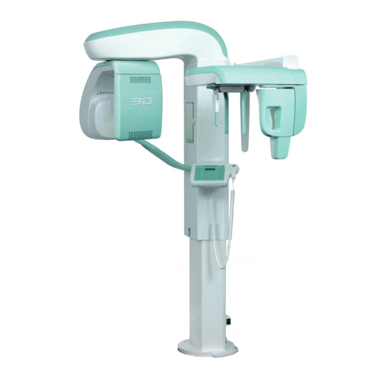
Villa Sistemi Medicali Rotograph EVO 3D Service Manual (290 pages)
Brand:
Villa Sistemi Medicali
| Category:
Medical Equipment
| Size: 14 MB
Table of Contents
Table of Contents
4
1 Introduction
10
Description of the System
11
Icons Appearing in the Manual
12
How to Contact VILLA SISTEMI MEDICALI Technical Service
12
2 Safety Information
14
Warnings
15
Distribution of Stray Radiation
18
Electromagnetic Emissions
19
Electromagnetic Immunity
20
Recommended Separation Distances for Non-Life Supporting Equipment
22
Environmental Risks and Displacement
23
Symbols Used
24
3 Description
26
Identification Labels and Laser Labels
26
Identification Plates and Laser Labels "220-240V" Version
27
Identification Plates and Laser Labels "110-120V" Version
28
Function, Models and Version
29
Basic Version
29
Version with Cephalometric Device
30
EVO XP (Extended Projection Package) - Optional
31
Block Diagram
32
Power Supply Assembly
33
CPU Board (A5 and A6)
34
CPU Board Jumper Configuration
35
Generator Board (A10) and Tubehead
36
Keyboard (A4)
37
Control Panel - Descriptions and Functions
39
Key Functions Description
42
4 Technical Data
44
Separate Parts Supplied with Rotograph EVO 3D
49
Applied Safety Regulations
51
Loading Curve of the Tube and Cooling Curve of the Anode
52
Measurement Method of Technical Factors
54
Dimensions
55
5 Pre-Installation
58
Electrical Setting up
59
Packaging
62
Space Requirements
63
Version Without CEPH
63
Version with CEPH
64
6 Installation
66
Setting of the Wall
67
Column Mounting
68
Mounting of the Rotating Arm Assembly
71
Mounting of CEPH-Arm (Optional)
76
How to Mount the Coverings
78
Inserting the CEPH Sensor in the Sensor Holder
79
Final Checks
80
PC - Rotograph EVO 3D Communication
80
PC - USB Protection Keys
80
PC Set up
80
DICOM Set-Up
81
Image Treatment Filters Setup
82
Verification of the PANORAMIC Function
83
Image Verification for the 3D Function
86
Verification of the CEPH Function
87
Invasive Method
93
Verification of Exposure Parameters
93
6.7.5.1.1. Kvp
96
6.7.5.1.2. Ma Check
97
6.7.5.1.3. Time
97
Non-Invasive Method
98
Storing of Automatic Exposure Parameters
100
Table of Pre-Set Anatomic Parameters
101
7 Troubleshooting
104
Leds
104
Generator Board A10 LED
104
CPU Board A5 LED
105
Displayed Messages
106
E108: Hardware Key Fault
110
E110: Battery Fault
110
Errors with Code from E000 to E199
110
E200: Zero Position Optical Sensor of Rotation Always Active / E201: Zero Position Optical Sensor of Rotation Never Active / E204: Unexpected Activation of Zero Position Rotation Sensor
111
Errors with Code from E200 to E299
111
E205 Timeout on Rotation
112
E206 Patient Collision
112
E240: Zero Position Sensor for y Axes Always Active / E241: Zero Position Sensor for y Axes Never Active / E242: Unexpected Activation of y Axes / E243: Timeout of y Axes
113
E280: Unexpected Activation of Zero Position Sensor on
114
E282: Zero Position Sensor for CEPH Never Active
114
E283: Zero Position Sensor for CEPH Always Active
114
CEPH Collimator Always Active
115
E300: Unexpected Activation of Zero Position Sensor on
115
E302: Zero Position Sensor for Secondary CEPH Collimator
115
Errors with Code from E300 to E399
115
Secondary CEPH Collimator / E301: Timeout of Zero
115
E320: Unexpected Activation of Zero Position Sensor on
116
E340: Sensor Holder Not in PAN Position
118
E360 and E361: X-Ray Button Pressed During Power on
119
E362: X-Ray Button Released During the Examination Procedure
120
E380: Invalid Canbus Message (from Generator CPU Board A9)
120
E381: Timeout on Activating CAN Protocol on Generator Board / E382: HF Not Answering to CAN Protocol
121
E400: Timeout of Zero Position Sensor on Soft Tissue Filter / E401: Zero Position Sensor for Soft Tissue Filter Always Active
122
Errors with Code from E400 to E499
122
Errors with Code from E700 to E799
123
E750: no Power to the Generator Board
124
E751: over Voltage Kv
124
E752: Filament Overload / E753: Overload on Anodic Current
125
E754: Broken Filament
125
E756: PFC Failure
125
E755: Alarm "Backup Timer Intervention" / E758: Alarm "No X-Ray" / E759: Alarm "Unexpected Emission
126
E760: Alarm "NO RX Button Command
127
E762: Alarm "NO X-Ray Feedback
127
7.2.5.10. E775: RX Button Released During the Emission
128
E774: RX Button Not Pressed
128
E800: Timeout on CAN Activation for Vertical Motor
129
E801: ON/OFF Command for Vertical Motor Not Changed on Planned Time
129
Errors with Code E800 and E801
129
E831: CPU Board - VDSIB Communication Locked
130
Errors with Code E850, E851 and E852
131
E850: more than One Button Pressed During Power on
131
E851: Column up or Column down Pressed at Power on
131
E852: One Key Pressed During the Movement
132
Service Programs Descriptions
133
Accessing the Service Programs
134
General Information on the Use of Keyboard
135
Password 92: Configuration Menus
136
Language
137
Date-Time Set
138
Disable X-Ray
139
Display Brightness / Display Contrast
139
Key Click Sound / Key Click Volume
139
LED Brightness
139
Manage Pano Opt
140
Tooth Style
141
7.3.3.10. COLL Setup Type
142
7.3.3.11. STF Setup Type
142
Digital Mode
142
7.3.3.12. Sensor Handling
143
7.3.3.13. DSPU IP Address
144
7.3.3.14. DSPU NET Mask
144
7.3.3.15. QSD IP Address
144
7.3.3.16. QSD NET Mask
144
7.3.3.17. Enable 3D Sensor
144
Password 118: Axis Alignment Menu
145
Rotation Zero
147
Cassette Zero
148
Y Axis Zero
148
Primary Collimator PAN
149
Primary Collimator 3D
150
Password 124: CEPH Settings
151
Enable Sensor
152
Y Offset
153
Lining up Test
154
Rotation Offset
154
CEPH Secondary Collimator Zero
155
CEPH Sensor Zero
156
STF Zero
156
Password 112: Troubleshooting
157
Test Column
158
Test Input Ports
159
Pre-Heating Time
161
Preheating Level
162
PAN RX Emission / CEPH RX Emission
163
System / Burn-In
164
Show Configuration
164
8 Periodic Maintenance
166
Service Tools
168
Detector Calibration
169
9 Corrective Maintenance
178
Digital Sensor Replacement
178
Calibration File Installation
178
PLEORA PCB Communication Address Enabling (Pleora Mac Address)
179
PLEORA PCB Communication Set up
180
Digital Sensor or Tubehead Replacement
181
Panoramic X-Ray Beam Centering Verification
181
Image Adjustment
187
CPU Board Replacement
189
CEPH Digital Sensor Replacement
191
PC Replacement
191
Software Package
191
Dental Studio Installation
192
CEPH Sensor Calibration File Installation
193
Sensor Calibration Files Installation
193
Internal Network Set up
194
Direct Point-To-Point Connection between PC and Rotograph EVO 3D
196
CEPH Arm Aligment
197
Ear Rings Alignment
199
CEPH Sensor Centering
204
Secondary Collimator Centering
206
Soft Tissue Filter (STF) Adjustment
210
Schematics and Drawings
214
General Diagram
216
Lay-Out Column CPU PCB A1
225
Circuit Diagram Column CPU PCB A1
226
Lay-Out Keyboard PCB A4
229
Circuit Diagram Keyboard PCB A4
230
Lay-Out CPU PCB A5
234
Lay-Out Microprocessor PCB A6
244
Circuit Diagram Microprocessor PCB A6
245
Lay-Out and Circuit Diagram Rotation Group PCB A7
249
Lay-Out Generator CPU PCB A9
250
Circuit Diagram Generator CPU PCB A9
251
Lay-Out Generator PCB A10
253
Circuit Diagram Generator PCB A10
254
Lay-Out Power HUB PCB A21
258
Advertisement
Advertisement
Related Products
Villa Sistemi Medicali ENDOS AC
Villa Sistemi Medicali ENDOS ACP
VILLA SISTEMI MEDICALI ROTOGRAPH-D
Villa Sistemi Medicali Arcovis 3000
Villa Sistemi Medicali STRATO 2000 Digital
Villa Sistemi Medicali Visitor T15
Villa Sistemi Medicali Categories
Medical Equipment
Dental equipment
More Villa Sistemi Medicali Manuals
Login
Sign In
OR
Sign in with Facebook
Sign in with Google
Upload manual
Upload from disk
Upload from URL