
Related Manuals for piezosystemjena 12V40 Series


Summary of Contents for piezosystemjena 12V40 Series
- Page 1 sales@artisantg.com artisantg.com (217) 352-9330 | Click HERE Find the Piezosystem Jena 12V40 at our website:...
- Page 2 Instruction Manual Voltage Amplifier 12V40 Series Tel: +49(0)3641/66880 • Fax: +49(0)3641/668866 • • www.piezosystem.de info@piezojena.com Artisan Technology Group - Quality Instrumentation ... Guaranteed | (888) 88-SOURCE | www.artisantg.com...
-
Page 3: Table Of Contents
Table of Contents Introduction Certification of piezosystem jena Declaration of conformity Instructions for using piezoelectrical elements and power supplies Safety instructions Instructions for checking the function of the system / quick start How to operate the 12V40 7.1. Technical data 7.2. -
Page 4: Introduction
Introduction This manual describes the voltage amplifier series 12V40 from piezosystem jena. This series contains following amplifiers: 12V40, 12V40SG, 12V40CLE, 24V40, 24V40SG, 24V40CLE, 12V40C und 12V40CSG.This manual also offers you additional information about piezoelectric products. Certification of piezosystem jena The company piezosystem jena GmbH has been certified by DIN EN ISO 9001:2000. -
Page 5: Declaration Of Conformity
Declaration of conformity Tel: +49(0)3641/66880 • Fax: +49(0)3641/668866 • • www.piezosystem.de info@piezojena.com Artisan Technology Group - Quality Instrumentation ... Guaranteed | (888) 88-SOURCE | www.artisantg.com... -
Page 6: Instructions For Using Piezoelectrical Elements And Power Supplies
Instructions for using piezoelectrical elements and power supplies Piezoelectric actuators from piezosystem jena are controlled by voltages up to 150V. These values can be quite hazardous. Therefore read the installation instructions carefully. Only authorized personal should handle the power supply. After transportation, piezoelectric actuators should be allowed to adapt for approximately 2 hours to the room temperature before being switched on. -
Page 7: Safety Instructions
Safety instructions Do not open the units! There are no user serviceable parts inside. Opening or removing covers may expose you to dangerous shock hazards or other risks. For servicing please refer to qualified service personnel. Allow adequate ventilation around the units so that heat can properly dissipate. -
Page 8: Instructions For Checking The Function Of The System / Quick Start
Instructions for checking the function of the system / quick start When you open the package, please check to make sure all the necessary parts are complete (see packing list) and nothing is damaged. Check the electronics and the actuator for any visible damage: The top and bottom plate of the actuator (if it does not have another shape) should be parallel each to each other, without scratches. -
Page 9: How To Operate The 12V40
(12V40CLE) measuring system connector LEMO 0S.304 (12V40SG) ODU 4pin series L (12V40CLE) table 1: technical data 12V40 series Tel: +49(0)3641/66880 • Fax: +49(0)3641/668866 • • www.piezosystem.de info@piezojena.com Artisan Technology Group - Quality Instrumentation ... Guaranteed | (888) 88-SOURCE | www.artisantg.com... -
Page 10: Initialization
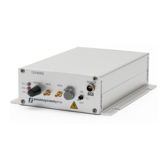
7.2. Initialization Please connect the device with the wall outlet by using the external power supply. It must be suitable to the type of amplifier. The power LED ON lights up after the power supply is switched on. Pay attention to the correct assignment of modulation signal and monitor signal on the front-panel SMB sockets, if you use this. -
Page 11: Smb Modulation Input: Mod
7.4. SMB modulation input: MOD The motion of the actuator may be remotely controlled by using this input. The control signal must be in the range of 0 ... +10V. There is an internal addition of the MOD signal and the adjusted OFFSET potentiometer. If there is an HIGH TTL level at the Pin8 of the rear panel connector, OFFSET and MOD (modulation input) are switched off. -
Page 12: Wiring Of The Rear Panel Connector
7.8. Wiring of the rear panel connector To realize OEM applications, all main control signals are available at the rear panel connector too. name description ground (Signal) +5V output, for switching SRC monitor signal 0...+10V modulation input 0...+10V source, choice of the amplifier control by HIGH or LOW TTL level HIGH: Pin 7 is active, OFFSET potentiometer and MOD (modulation input) at the front panel are switched off... - Page 13 The voltage amplifier 12V40C/ CSG do not have a casing. They should be integrated into costumer systems for OEM applications. name description 1,2,8,9 GND ground (Signal) +5V output, for switching SRC monitor signal 0...+10V modulation input 0...+10V source, choice of the amplifier control by HIGH or LOW TTL level HIGH: Pin 7 is active, OFFSET potentiometer and MOD (modulation input) at the front panel are switched off...
-
Page 14: Possibilities Of The Error Correction
7.9. Possibilities of the error correction Please check the power cord at first, if the system does not works properly. error possible correction ON-LED is off please check the power supply OVL or UVL-LED flash over- or underload, please check the modulation input and offset table 4: possibilities of the error correction The equipment concept makes adaptations to customer preferences,... -
Page 15: Your Notes
Your notes Tel: +49(0)3641/66880 • Fax: +49(0)3641/668866 • • www.piezosystem.de info@piezojena.com Artisan Technology Group - Quality Instrumentation ... Guaranteed | (888) 88-SOURCE | www.artisantg.com...
Need help?
Do you have a question about the 12V40 Series and is the answer not in the manual?
Questions and answers