Table of Contents
Advertisement
Quick Links
Bedienungsanleitung
Spannungsverstärker
instruction manual
voltage amplifier
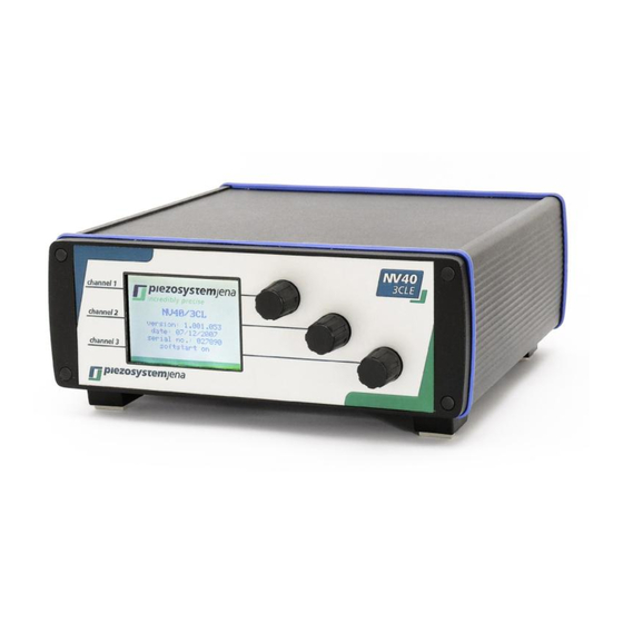
NV40/3
NV40/3CLE
NV120/1
NV120/1CLE
Bitte lesen Sie sorgfältig die Bedienungsanleitung vor dem Einschalten des Gerätes. Beachten Sie
bitte insbesondere die Sicherheitshinweise!
Read carefully before switching on the power! Please see also instructions for safety when using
piezoelectric actuators and power supplies!
Geschäftsführer: Dr. Bernt Götz • Telefon 03641/66880 • Fax 03641/668866 • www.piezojena.com
1
Advertisement
Table of Contents

Related Manuals for piezosystemjena NV40/3


Summary of Contents for piezosystemjena NV40/3
- Page 1 Bedienungsanleitung Spannungsverstärker instruction manual voltage amplifier NV40/3 NV40/3CLE NV120/1 NV120/1CLE Bitte lesen Sie sorgfältig die Bedienungsanleitung vor dem Einschalten des Gerätes. Beachten Sie bitte insbesondere die Sicherheitshinweise! Read carefully before switching on the power! Please see also instructions for safety when using piezoelectric actuators and power supplies! Geschäftsführer: Dr.
-
Page 2: Table Of Contents
....................... 33 installation, power supply .................... 34 operation........................34 maintenance and inspection ..................35 environmental conditions .................... 35 NV40/3, NV40/3CLE, NV120/1 and NV120/1CLE ............36 key words ........................36 user elements / connections ..................37 7.2.1 front panel ........................37 7.2.2... -
Page 3: Introduction
1 introduction This manual describes the piezo amplifiers NV40/3, NV40/3CLE, NV120/1 and NV120/1CLE from piezosystem jena. You will also find additional information regarding piezoelectric products. definition: All systems from piezosystem jena such as electronics, actuators and optical systems are called units. -
Page 4: Declaration Of Conformity
This instruction manual includes important information for using piezo actuators. Please take time and read this information. Piezo positioning systems are mechanical systems with highest precision. Correct handling guarantees the precision over long time. 3 declaration of conformity Geschäftsführer: Dr. Bernt Götz • Telefon 03641/66880 • Fax 03641/668866 • www.piezojena.com... -
Page 5: Purchased Part Package
4 purchased part package Please check the completeness of the delivery after receiving the shipment: voltage amplifier NV40/3 (NV40/3CLE, NV120/1, NV120/1CLE) wide range power supply 24VDC MOD/MON cable RS232 cable USB cable instruction manual CD-ROM with drivers, software and instruction manual 5 instructions for using piezo electrical elements and power supplies Piezoelectric actuators from piezosystem jena are controlled by voltages up to 150V. -
Page 6: Safety Instructions
6 safety instructions Icons: RISK OF ELECTRIC SHOCK! Indicates that a risk of electric shock is present and the associated warning should be observed. CAUTION! REFER TO OPERATOR´S MANUAL – Refer to your operator’s manual for additional information, such as important operating and maintenance instructions. RISK OF ELECTRIC SHOCK! Do not open the units! There are no user serviceable parts inside and opening or removing covers may expose you to dangerous shock hazards or other risks. -
Page 7: Installation, Power Supply
6.1 installation, power supply RISK OF ELECTRIC SHOCK Do not insert or unplug the power plug with wet hands, as this may result in electrical shock. Do not install in rooms, where inflammable substances are stored. If flammable substances come into contact with electrical parts inside, this may result in fire or electrical shock. Do not damage or modify the power cord. -
Page 8: Maintenance And Inspection
6.3 maintenance and inspection CAUTION! When cleaning the exterior box of the voltage amplifier, first turn off the power switch and unplug the power plug. Failure to observe these items may result in a fire or electrical shock. Cleaning the exterior box using a firmly wrung-out cloth. Do not use alcohols, benzene, paint thinner or other inflammable substances. -
Page 9: Nv40/3, Nv40/3Cle, Nv120/1 And Nv120/1Cle
7 NV40/3, NV40/3CLE, NV120/1 and NV120/1CLE These voltage amplifiers are very similar. In case of information which do refer to the NV40/3CLE or NV120/1CLE the symbol “ → not available in NV40/3, NV120/1” will point it. NV40/3 piezo amplifier for up to 3 PZT actuators; RS232/USB interface; for piezo actuating systems... -
Page 10: User Elements / Connections
PC INTERFACE serial RS232 interface or USB1.1 (see 8.3) REMOTE CONTROL The remote control switches all manual controls (ENCODER KNOB and MODULATION) off or on. Please pay attention only if the remote control is switched on (1) it will be possible to use the „set“... -
Page 11: Back Panel
7.3 introduction The amplifiers NV40/3 and NV40/3CLE are designed for parallel control of up to three low voltage piezo actuators with and without internal feed back sensor system. NV120/1 and NV120/1CLE are designed for control of one low voltage piezo actuators with higher output current. -
Page 12: Block Diagram
Please follow all safety instruction given in chapter 6 before using the amplifier. 7.4.1 main supply voltage The amplifier NV40/3, NV40/3CLE, NV120/1 and NV120/1CLE require a main supply voltage of 24VDC. A power supply unit suitable for voltages from 100 up to 240Volt AC is included in the shipment. -
Page 13: Connecting Piezo Actuator
„OVL“, „UDL“ (only NV40/3CLE) internal temperature 7.4.4 graphic display NV120/1, NV120/1CLE The graphic display shows the same status information as the NV40/3, NV40/3CLE but only for one channel. Geschäftsführer: Dr. Bernt Götz • Telefon 03641/66880 • Fax 03641/668866 • www.piezojena.com... -
Page 14: Handling
8 handling 8.1 manual control Each channel can be controlled by turning the encoder knob on the front panel. Turning clockwise increases the applied voltage signal, turning counter clockwise reduces the applied voltage signal. Depend on how fast the knob is turned, the change of the applied signal can be adjusted. -
Page 15: Monitor Nv40/3, Nv120/1
The command “monwpa” is deactivated. 8.2.3 monitor NV40/3, NV120/1 The monitor output of the NV40/3, NV120/1 always provides a signal of 0V up to +10V which directly corresponds to the voltage signal applied to the piezo actuator. The command „monwpa“... -
Page 16: Controlling Via Interface
8.3 controlling via interface The amplifier series NV 40/3 and NV 120/1 can be controlled via RS232 interface. Therefore signal parameters and information about the actuator position or status can be adjusted or settled directly. Furthermore, the system settings of the amplifier unit can be changed by using the interface. -
Page 17: Command List Overview
NV40/3CLE, NV120/1CLE or voltage (only NV40/3, NV120/1) only for one channel measure gives values of all channels either for position () or voltage monwpa... -
Page 18: Commands
8.3.3 commands command 'setk' call: setk,<ch>,<0|1> example: setk,0,1 answer: none set the actuator on channel 0 (PIEZO 1) to remote control The command setk switches the remote control for one channel <ch> on <1> or off <0>. If the remote control is activated you won't be able to change the position neither by the ENCODER KNOB nor via MODULATION. - Page 19 readout value is given with 3 decimal places. command 'measure' call: measure example: measure answer: aw,<value0>,<value1>,<value2> aw,0.015,5.003,150.002 The command „measure“ reads out either the position <value0, 1, 2> from the measuring system in closed loop () or the voltage applied to the actuator in open loop. The readout values <value0, 1, 2>...
-
Page 20: Examples
[Enter] NV403CLE> (NV403, after pressing the [Enter] key on the computer keyboard the prompt shows “NV403CLE>” NV120CLE, NV120) (NV40/3, NV120/1CLE, NV120/1) in the HYPER TERMINAL program setk,0,1 none activates the remote control on channel 0 cloop,0,1 none switches channel 0 to closed loop mode... -
Page 21: Calibration Of Encoder
4: example for remote control NV120/1CLE 8.3.5 calibration of encoder The encoder of NV40/3[CLE] e.g. NV120/1[CLE] is used for the calibration of the attached actuator in open and closed loop. The encoder has a resolution of 30 detent / rotation. - Page 22 special commands for encoder: normal with acceleration (EM0) call: encexp,<1...10> example: encexp,3 answer: none the exponent is set to 3 adjustable interval with and without acceleration (EM1,2) call: encstol,<0.001…150.000> example:encstol,1.000 the step size for„open loop“ is set to 1V answer: none The numerical resolution of 1mV will be not achieved due to the resolution of the DAC of 16 bit.
-
Page 23: Technical Data
(wide range power supply 100-240VAC is included in the shipment) NV40/3 – E-101-20 order info NV40/3CLE – E-101-23 NV120/1 – E-101-90 NV120/1CLE – E-101-93 chart 5: technical data NV40/3 [CLE], NV120/1 [CLE] Geschäftsführer: Dr. Bernt Götz • Telefon 03641/66880 • Fax 03641/668866 • www.piezojena.com... -
Page 24: Pin Assignment
8.5 pin assignment 8.5.1 output connector for actuator D-SUB15pin The D-SUB 15 connector for the piezo actuating system has two functionalities. First, connection for the voltage signal of the piezo control, and second, the voltage supply for the feed back sensors, when a closed loop system is used. -
Page 25: Rs232 D-Sub9Pin
Chart 9: USB-connector NV40/3CLE, NV120/1CLE 8.5.5 main supply voltage The NV40/3, NV40/3CLE, NV120/1 and NV120/1CLE needs 24VDC and require at least a current of 2.5A. The 2.1mm barrel connector has the following layout. A wide range power supply 100-240VAC is included in the shipment. -
Page 26: Trouble Shooting
9 trouble shooting During operation the display can show a defined error code. A reason can be the buffer overflowing, a temperature value out of range or a overshooting of the actuating system. Promptly the error code is provided on the display and on the connected PC too. The code is 16bit wide and it’s binary-coded (ERROR,FWch0,FWch1,FWch2). -
Page 27: Your Notes
your notes Geschäftsführer: Dr. Bernt Götz • Telefon 03641/66880 • Fax 03641/668866 • www.piezojena.com...
Need help?
Do you have a question about the NV40/3 and is the answer not in the manual?
Questions and answers