Table of Contents
Advertisement
Quick Links
Instruction Manual
Digital Piezo Amplifier
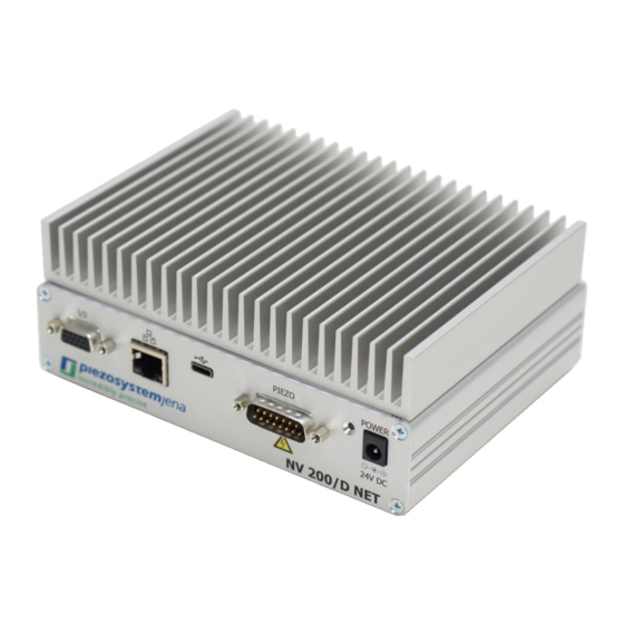
NV200/D NET
Please read caref ully bef ore switching on the power! Please see saf ety instructions f or
using piezoelectric actuators and power supplies!
21.12.2021
Rev 0
1
CEO: Dr. Bernt Götz • Phone +493641/66880 • Fax +493641/668866 • www.piezosystem.com
Advertisement
Table of Contents

Related Manuals for piezosystemjena NV200/D NET


Summary of Contents for piezosystemjena NV200/D NET
- Page 1 Instruction Manual Digital Piezo Amplifier NV200/D NET Please read caref ully bef ore switching on the power! Please see saf ety instructions f or using piezoelectric actuators and power supplies! 21.12.2021 Rev 0 CEO: Dr. Bernt Götz • Phone +493641/66880 • Fax +493641/668866 • www.piezosystem.com...
- Page 2 CEO: Dr. Bernt Götz • Phone +493641/66880 • Fax +493641/668866 • www.piezosystem.com...
-
Page 3: Table Of Contents
Maintenance and inspection ......................8 Environmental conditions ....................... 8 Instructions for checking the function of the system / quick start ............8 How to operate the digital amplifier NV200/D NET ................9 Introduction............................9 Technical data ..........................10 Connectors and Pin Assignment ....................11 Establishing communication ...................... -
Page 4: Introduction
1 Introduction This manual describes the digital piezo amplifier series NV200/D NET from piezosystem jena. You will also find additional information regarding piezoelectric products. Definition: All systems from piezosystem jena such as electronics, actuators, and optical systems are called “units”. -
Page 5: Purchased Part Package
4 Purchased part package Please check the completeness of the delivery after receiving the shipment: • piezo amplifier NV200/D NET • wide range power supply 24 VDC For optional needed drivers or available software see our homepage. 5 Instructions for using piezo electrical elements and power supplies •... -
Page 6: Safety Instructions
6 Safety instructions 6.1 Icons RISK OF ELECTRIC SHOCK! Indicates that a risk of electric shock is present and the associated warning should be observed. CAUTION! REFER TO OPERATOR´S MANUAL – Refer to your operator’s manual for additional information, such as important operating and maintenance instructions. RISK OF ELECTRIC SHOCK! •... -
Page 7: Installation & Power Supply
6.2 Installation & power supply RISK OF ELECTRIC SHOCK! • Do not insert or unplug the power plug with wet hands, as this may result in electrical shock. • Do not install in rooms where inflammable substances are stored. If flammable substances come into contact with electrical parts inside, it could result in fire or electrical shock. -
Page 8: Maintenance And Inspection
Maintenance and inspection CAUTION! • Before cleaning the exterior box of the voltage amplifier, turn off the power switch and unplug the power plug. Failure to do so may result in a fire or electrical shock. • Clean the exterior box using a damp cloth that has been firmly wrung-out. Do not use alcohols, benzene, paint thinner or other inflammable substances. -
Page 9: How To Operate The Digital Amplifier Nv200/D Net
The actuator is connected to the NV200/D NET using the “PIEZO” plug. After switch on, the device runs a self-test procedure, while the indicator LED is lightning red. This takes about 3 s. During this step the controller reads the system specific parameters from the actuators ID-chip and sets up the controller. -
Page 10: Technical Data
8.2 Technical data Input voltage 24 V Power supply connector low voltage socket with 2.1 mm pin Input current max. 2 A (rms) / 7 A (peak) @ 24 V, idle current 110 mA Power consumption max. 48 W -10 V ... +180 V or -20 V … +130 V Output voltages (automatically adapted to the actuator) 200 mA (continuous) -
Page 11: Connectors And Pin Assignment
8.3 Connectors and Pin Assignment 8.3.1 Overview Status Power supply Ethernet Piezo actuator connector connector connector connector connector connector CEO: Dr. Bernt Götz • Phone +493641/66880 • Fax +493641/668866 • www.piezosystem.com... - Page 12 8.3.2 Piezo actuator connector Type: 15 pin D-SUB plug Label Description 1, 2, 11 AGND Analog ground +15 V* Operating voltage measurement +15 V 4, 14 Digital ground I²C-Bus SDA 3.3 V Supply voltage ID-Chip eeprom actuator +180 V … -20 V ®...
- Page 13 8.3.3 I/O connector Type: 15 pin D-Sub HD jack Label Description Analog modulation input (0...10V), (Impedance 1 MΩ) MON2 Not used Trigger input (TTL, 0 / 3,3V…5V) TRG in SPI: CLK SPI clock (3,3V logic, slave input) DGND Digital ground (for SPI & Trigger) AGND Analog ground (for MOD &...
-
Page 14: Establishing Communication
8.4 Establishing communication 8.4.1 Serial communication via USB The NV200/D NET can easily communicate with your PC with the use of a terminal program such as HTerm. A USB connection cable (included) is required to connect to your computer. The properties of the COM port are: 115200 baud, 8 bit, no parity, 1 stop bit, software handshake (XON / XOFF). - Page 15 Alternatively, you can use other programs like Putty. After successful connection the full command set is available. The Telnet connection can be established via the IP address of the controller and the correct port number. The default port number is 23. By default, the IP address is set dynamically over DHCP.
- Page 16 8.4.3 Ethernet configuration The network settings can be changed via Telnet connection (port: 9999) or via a web browser. It is possible to change the IP address and the default port (23) for Telnet communication with the device. Under the item “Server” the IP address can be set to a static one or to DHCP. Under item “Channel 1”...
- Page 17 8.4.4 SPI communication Real-time communication can take place via the SPI interface. The device works as an SPI slave, i.e. the device receives setpoints from an external SPI master. The return value retrieved over the MISO channel can be set to different quantities (e.g. position values) via the USB or Ethernet interfaces. The SPI connection is exclusively to send setpoints to the device.
-
Page 18: Command List
To synchronize the NV200/D NET PID controller loop execution to the SPI master the spitrg option can be used. In mode spitrg,0 the internal 20 kHz clock is used to trigger the digital control loop interrupt. In mode spitrg,1 the digital control loop interrupt is executed only when a new SPI setpoint is received. - Page 19 0 = set-Command via USB or Ethernet modsrc Signal source for setpoint 1 = Analog In 2 = SPI 3 = Arbitrary waveform generator monsrc Source of data for analog output 0 = position (closed loop) 1 = setpoint 2 = piezo voltage (controller output) 3 = position error 4 = abs(position error) 5 = position (open loop)
- Page 20 recsrc Source of data to be stored in data recorder channel 0 = buffer A recsrc,<ch>,<src> 1 = buffer B src: 0 = piezo position in µm or mrad 1 = setpoint in µm or mrad 2 = piezo voltage in V (controller output, not amplifier output) 3 = position error 4 = abs(position error)
- Page 21 1 = position (closed loop) 2 = setpoint 3 = piezo voltage (controller output) 4 = position error 5 = abs(position error) 6 = position (open loop) 7 = piezo current 1 8 = piezo current 2 9 = test value (0x5A5A) spitrg Set the PID control loop interrupt source 0 = internal...
-
Page 22: Error Messages
domain in1) With index (up to in1) = output of the value at index Read the correction type in frequency domain 0 = no learning 1 = learning based on offline identification 2 = learning based on online identification isave Save learned profiles in the actuator iload Load learned profiles from the actuator... -
Page 23: Status Register
8.7 Status register The status register is a 16bit register, in which each bit describes a certain setting of the amplifier or actuator. The decimal sum of all bits is the value of the status register. It can be requested by the stat command. -
Page 24: Feedback Control Modes
8.8 Feedback control modes 8.8.1 PID control The following block diagram shows the functional groups of the controller in PID mode (ctrlmode,0): CEO: Dr. Bernt Götz • Phone +493641/66880 • Fax +493641/668866 • www.piezosystem.com... - Page 25 When any actuator made by piezosystem jena is connected to the NV200/D NET its specific values are read from the actuator’s ID-chip. The controller is then automatically configured with these values.
- Page 26 8.8.2 ILC control Iterative learning control is a method to iteratively determine the required piezo voltage profile to perfectly track a desired position profile. The only restriction is that the desired position profile is periodic. Therefore, it must be possible to define the constant position profile in the time window �� = [0;...
-
Page 27: Arbitrary Waveform Generator
8.9 Arbitrary waveform generator rbitrary waveform g can generate a single or repetitive setpoint signal. The curve shape enerator can be freely defined by up to 1024 samples. gsarb goarb gearb gtarb gbarb gcarb After the command grun,1 the starts at the index defined by goarb and rbitrary waveform g enerator runs until the index defined by gearb. -
Page 28: Data Recorder
Various controller functions can be carried out with the trigger input. This can be used to synchronize the controller with several other NV200/D NET controllers or any other external device. The trigger input uses a 5V logic and is activated by rising edges. -
Page 29: Temperature Measurement
8.11.2 Trigger Out In order to control external devices, the measured or desired (setpoint) position can be reported back via the trigger output. The input signal for the trigger can be chosen via trgsrc command. The trigger signal is low-active, i.e. an H / L edge shows that a trigger point has been reached. The signal range in which trigger events are generated is determined with trgss (lower limit) and trgse (upper limit). -
Page 30: Troubleshooting
9 Troubleshooting Please check all cables and connections first if the system is not working properly. Error Possible cause and fix LED lights red No connection between actuator and amplifier. Check the actuator cable for damage. LED blinks red nanoX mode is not possible on this device. Actuator oscillates in Unsuitable PID parameters.
Need help?
Do you have a question about the NV200/D NET and is the answer not in the manual?
Questions and answers