Table of Contents
Advertisement
Quick Links
Advertisement
Table of Contents

Related Manuals for Xylem SI Analytics TITRATOR TitroLine 7500 KF


Summary of Contents for Xylem SI Analytics TITRATOR TitroLine 7500 KF
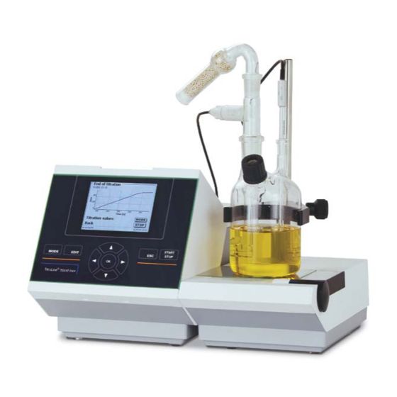
- Page 1 OPERATING INSTRUCTIONS 7500 KF trace ® TitroLine TITRATOR...
- Page 2 Gebrauchsanleitung Seite 3 ..58 Originalversion .................. Wichtige Hinweise: Die Gebrauchsanleitung vor der ersten Inbetriebnahme des Titrators TitroLine® 7500 KF trace bitte sorgfältig lesen und beachten. Aus Sicherheitsgründen darf der Titrator TitroLine® 7500 KF trace ausschließlich nur für die in dieser Gebrauchsanleitung beschriebenen Zwecke eingesetzt werden. Bitte beachten Sie auch die Gebrauchsanleitungen für die anzuschließenden Geräte.
-
Page 3: Table Of Contents
TABLE OF CONTENT PAGE Technical Specifications of the Titrator TitroLine® 7500 KF trace ...... 59 Summary ..........................59 Specifications Titrator TitroLine® 7500 KF trace ..............60 Warning and safety information ....................63 Unpacking and First Operation ................64 Unpacking ..........................64 Connection and installation of titrator and magnetic stirrer TM 235 ........ - Page 4 Connection of Analytical Balances and Printers ..........106 Connection of Analytical Balances ..................106 7.1.1 Balance TZ-Number ......................106 Balance data editor ....................... 107 Connection of Printers ......................108 Maintenance and Care of the TitroLine® 7500 KF trace ........109 Storage and transportation ...................
-
Page 5: Technical Specifications Of The Titrator Titroline® 7500 Kf Trace
Technical Specifications of the Titrator TitroLine® 7500 KF trace 1.1 Summary The TitroLine® 7500 KF trace is suitable for the following applications: The possible range of titrations includes coulometric KF titrations with a maximum of 50 memorisable methods. The TitroLine® 7500 KF trace can be used as stand-alone instrument or in combination with a heating oven. General provisions: The safety guidelines that are applicable to the handling of chemicals have to be observed under all circumstances. -
Page 6: Specifications Titrator Titroline® 7500 Kf Trace
1.2 Specifications Titrator TitroLine® 7500 KF trace Status Nov 21, 2013 CE sign: EMC compatibility according to the Council Directive: 2004/108/EG; applied harmonized standards: EN 61326-1:2006 Low-voltage directive according to the Council Directive 2006/95/EG Testing basis EN 61 010, Part 1 ETL sign: Conforms to ANSI/ UL Std. - Page 7 USB –Typ A (“master“) for connecting: - USB keyboard - USB printer - USB data media e.g. USB stick - USB Hub Stirrer connection: 12V DC out, 500mA power supply for stirrer TM 235 or titration stand TM 235 KF Housing material: Polypropylene Front keyboard:...
- Page 8 Specifications Titration Stand TM 235 KF Status Nov 21. 2013 In connection with the titrator TitroLine 7500 KF trace CE - Mark EMV – compatibility according to Council Directive 89/336/EWG; Transient emissions according to norm EN 50 081, part 1 Interference resistance according to norm EN 50 082, part 2 Low voltage directive according to Council Directive 73/23/EWG Last amended by directive 93/68/EWG;...
-
Page 9: Warning And Safety Information
1.3 Warning and safety information The TitroLine® 7500 KF trace corresponds to protection class III. It was manufactured and tested according to DIN EN 61 010, Part 1, Protective Measures for Electronic Measurement Devices and has left the factory in an impeccable condition as concerns safety technology. -
Page 10: Unpacking And First Operation
Unpacking and First Operation 2.1 Unpacking The titrator itself as well as all related accessory and peripheral parts have been carefully checked at the factory to ensure their correct function and size. . The different TitroLine® 7500 KF trace modules consists of: •... -
Page 11: Connection And Installation Of Titrator And Magnetic Stirrer Tm 235
2.2 Connection and installation of titrator and magnetic stirrer TM 235 The low voltage cable of the power supply TZ 1853 has to be plugged in to the 12 V socket „in“, (see Fig. 12 back panel, chapter. 2.7), on the back panel of the titrator. Then plug the power supply into the plug socket. Fig. -
Page 12: Installation With Magnetic Stirrer Tm 235 (Module 1 And 3)
2.3 Installation with magnetic stirrer TM 235 (module 1 and 3) The titrator TitroLine 7500 KF trace can be mounted on any desired plain basis. Prior to inserting the mains plug, it must be ensured that the operating voltage of the titrator complies with the mains voltage. Normally, this should not be a problem since the power pack is designed as a multiple voltage level power pack with a range of 100 –... - Page 13 Mount the retaining clip onto the stand rod Fig. 4 Clamp the titration vessel onto the retaining clip. Fix the titration vessel in such a way that the bottom of the titration vessel stands directly at the upper surface of the magnetic stirrer: Fig.
-
Page 14: Installation With Magnetic Stirrer/Pump Tm 235 Kf (Module 2 And 4)
Put the indicator electrode KF 1150 and the generator electrode (TZ 1752 or TZ 1753) into the provided openings NS 7,5 and NS 19 and the electrode cables into the colour-coded socket. The indicator electrode has a fixed cable with 2 blue plugs. The cable LB 04 NN has a green and black plug and is connected to the provided port of the generator electrode. - Page 15 Put all white inner plastic adapters to the waste, solvent and moisture bottle. Fill the moisture bottle with molecular sieve. Connect the PVC and PTFE plastic tubes as shown in the next pictures. The PVC tubes are connected to the connectors at the back side of the TM 235 KF. The long PVC tube is used for the connection of the waste bottle.
- Page 16 Put the other end of the PTFE-tube, which touches the bottom of the titration vessel (tube 1), through the opening on the cap of the clear square bottle (-> waste bottle). Put the other PTFE tube (tube 2) through the opening of the cap of the brown reagent bottle.
-
Page 17: Filling The Titration Vessel
If the reagents continue to run in from the storage bottle after the actual dosage process has ended, position the bottle at lower level than the titration vessel. If the reagents continue to run in from the storage bottle between the dosage process and the siphon off process, please wait a few seconds between the changes. -
Page 18: Connecting The Titrator - Combination With Accessories And Additional Devices
2.7 Connecting the Titrator - Combination with Accessories and Additional Devices 2.7.1 Back panel of the titrator TitroLine® 7500 KF trace Fig. 12 2.7.2 Connection ports of the TitroLine® 7500 KF trace The TitroLine® 7500 KF trace is equipped with the following connections: 1) µA measurement input for the connection of double platinum electrodes (KF 1100 or Pt 1200, Pt 1400) 2) USB-B interface for connection to a PC 3) On/Off switch... -
Page 19: Connection Of Analytical Balances
2.7.5 Connection of analytical balances Analytical balances are to be connected to the RS232-2 using an appropriate cable 2.8 Setting the Language of the Country The ex-factory default language setting is English. When the piston burette is switched on, the main menu will appear once the boot sequence is completed: Fig. -
Page 20: Working With The Titrator Titroline® 7500 Kf Trace
Working with the Titrator TitroLine® 7500 KF trace 3.1 Front Keyboard Apart from alphanumeric input (a-z, A-Z, 0-9) and a few other functions, almost all functions can be performed using the front keyboard. <Mode>: Methods selection and system settings <EDIT>: Changing the current method, new method, copy, print and delete method <ESC>: <ESC>... -
Page 21: External Pc Keyboard
3.3 External PC Keyboard Keys Function <ESC> <ESC> will take the user to the previous level on the menu. <F1>/<START> Start of a selected method <F2>/<STOP> Stop of the current method <F3>/<EDIT> Change of the current method, new method, copy method <F4>/<FILL>... -
Page 22: Menu Structure
3.4 Menu Structure There are 4 selection menus: • Start or main menu • Method parameters • Method selection • System settings After power-up, the main menu is always the first menu to appear. The method displayed will always be the last method that was used (Fig. - Page 23 <MODE>/F6 leads you to the “select method“ menu: Fig.18 Existing methods can be selected by pressing the <↓> und <↑> keys and confirming the selection with <OK>/<ENTER>. Once the selection made, you will return to the main menu with the newly selected method. If no method is selected, <ESC>...
-
Page 24: Main Menu
3.5 Main Menu After power-up, the main menu is always the first menu to appear. The method displayed will always be the last method that was used. Fig. 21 3.5.1 Starting a Titration Once all preparations have been finished, you can start to titrate samples. The titrator starts automatically with the conditioning process when it switched on and anolyte is present in the titration vessel. - Page 25 Fig. 24 The balance data can be entered using the front keyboard or an external keyboard. The input is to be confirmed with <OK>/<ENTER>. In the case of an automatic acceptance of the balance data, the weighed-in quantities will be read in from a memory.
- Page 26 Fig. 27 Scaling of the chart will be done automatically. The result will be displayed at the end of the titration Fig. 28 <MODE>/<F6> can be used to view the titration curve or further results: Fig. 29 If a printer is connected, the results will either be printed according to the settings made for the method, or else they will be memorised in the form of a PDF- and CSV-file file on a connected USB stick.
-
Page 27: Method Parameters
Method Parameters From the main menu (Fig. 21), <EDIT>/<F3> will take you to the method parameters: Fig. 30 4.1 Method editing and new method If you select <edit method> or <new method> you will be taken to the modification or new creation of a method. Selecting <new method>... -
Page 28: Copy Methods
Once the selection made, you are directly prompted for the input of the method name. Fig. 33 The standard name may be adopted or modified. Subsequently, you will be taken to the <Change method parameters> item. Please continue at this point with Chapter 4.6. 4.3 Copy Methods Methods can be copied or stored with a new name. -
Page 29: Print Method
4.5 Print method The currently selected method can be printed on a connected printer or stored on an USB drive as PDF file Fig. 36 4.6 Change Method Parameters The input or modification of the method name was already described in Chapters 4.1. Fig. - Page 30 4.6.1.1 Result text The result text is used in the result display and printouts. It can be changed from “result” to any other alphanumeric name. For KF titration “water” is useful. Fig. 39 4.6.1.2 Calculation Formula The appropriate calculation formula is selected on the Formula selection submenu: Fig.
- Page 31 After selecting a formula, please confirm your selection with <OK>/<ENTER>: Fig. 41 The values for the blank value and the factors can be entered manually or read from a global memory. The values from a global memory were defined in advance by a titration or were manually entered. Fig.
- Page 32 Storing results in global memories is described in Chapter 4.6.1.7 The values of the individual parameters of the selected calculation formula can now be input one by one. Fig. 45 4.6.1.3 Sample weight and volume (sample quantity) Fig. 46 Fig. 47 The Sample Quantity (W) item is used to select whether one is wishing to use a sample weight or a sample volume for titration or solution preparation.
- Page 33 4.6.1.4 Formula unit The formula unit can be selected in the Unit submenu. Fig. 48 Once the selection made (e.g. % or ppm), the unit will also be displayed as piece of information on the display. Fig. 49 4.6.1.5 Decimal digits To conclude, it is possible to determine the number of decimal digits from 0-6.
- Page 34 Fig. 51 The calculation of the mean value is already possible from two individual values. The calculation of the relative standard deviation is only possible from 3 single values. The maximum quantity is 10. Fig. 52 The mean value and the relative standard deviation (RSD) are shown directly on the display or in the result printout.
- Page 35 Fig. 54 This simplifies later the allocation of the global memory in another method. Example: The result from blank titration is defined with the support of an extra method. The result in µg is thereby automatically written into global memory M01 by using the name "blank value extern. Fig.
-
Page 36: Titration Parameters
4.6.2 Titration parameters The <Titration parameter> submenu is used to determine the actual parameters of the method: Fig. 57 Generally applicable titration parameters The following parameters can be adjusted: • Start drift • Control factor End criteria: • Maximum titration time •... - Page 37 Fig. 59 Max. Titration Time The maximum titration time is used with samples that generate an increased drift in the end and when it is not possible to achieve stable end values. The max. titration time can be adjusted from 0 to 9999 s. The standard value is pre-set to 600 s.
- Page 38 Fig. 62 Working point The working point in mV is the base value for the indicator electrode. It can be set from 1 to 1000 mV. 300 mV is pre-set as standard value and works for many reagent/reagent combinations. A higher value is maybe sometimes necessary.
- Page 39 This means: The lower the entered stop drift, the longer takes the measurement. If a high stop drift (e.g. 20 µg/min) is entered, the measurement ends significantly faster. Low value = exact measurement, high value = inexact measurement. As stop drift 2 µg/min are pre-set as standard value. The value can be entered from 0.01 to 25 µg/min.
-
Page 40: Sample Identification
If the drift change is within the stop drift tolerance during the entire follow-up time, the measurement will be ended. Diagram 2: The criterion stop drift as difference to the start drift, the stop drift tolerance as stability criterion for the drift. -
Page 41: Documentation
Fig. 67 After a new power-up, numbering will resume with 01. 4.6.4 Documentation Fig. 68 Three different format settings are available for documentation on a printer or USB device: “short”, “standard (with curve)” and “GLP”: Fig. 69 Short documentation Standard GLP-Documentation documentation Method name, date, time, duration of... -
Page 42: System Settings
System settings Fig. 70 From the main menu (Fig. 72), <SYS>/<F7> will get you to the system settings: Fig. 71 Setting the national language was already described in Chapter 2 5.1 Global Memory The handling with the global memories were already described in the chapter 4.6.1.7. 5.2 RS232 Settings The <RS232 settings>... - Page 43 Fig. 73 The baud rate is preset to 4800. It may be set to 1200 – 19200: Fig. 74 Fig. 75 The parity can be selected amongst <No>, <Even> and <Odd>. <No> is the default setting. Fig. 76 You may select between 7 and 8 data bits. 8 bits is the default setting.
-
Page 44: Date And Time
Fig. 77 The RS232 parameters can be set to the factory settings. 5.3 Date and Time The factory time setting is Central European Time. This setting may be changed, where necessary: Fig. 78 5.4 Password The activation of the password has not yet been implemented for the current version 13_12t. Please contact SI Analytics for sending you an update version. -
Page 45: Printer
5.6 Printer For connecting printers please refer to chapter 7.3. Fig. 80 5.7 Device Information <Device Information> contains information about • the current software version • the serial number of the device • printer driver and update version • device address •... -
Page 46: Data Exchange
Fig. 82 No sounds will occur when the external keyboard is used. 5.9 Data exchange All methods with all parameter settings and global memories can be stored and restored on a connected USB- memory. It is also possible to transfer the settings from one titrator to another one. The backup will be started with Settings backup: Fig. - Page 47 Fig. 85 The backup folder on the USB-memory Stick starts with the backup date. Here it is 130325_1132382_Setti… That means the backup is from 25 March 2013 11.32 hour: Fig. 86 Confirm the selection with Enter. During the restoring process of the backup appears “Settings are being restored”...
-
Page 48: Software Update
5.10 Software Update Fig. 88 An update of the device software requires a USB stick containing a new version. For this operation, the two files that are needed have to be located in the root directory of the USB device: Plug the USB device into a free USB-A port, wait for some seconds, and then select the Software Update function. - Page 49 Fig. 90 which will change after a few seconds to the following display: Fig. 91 Upon completion of the update (approx. 2-3 minutes), the device will shut down the software completely and proceed to a new start. Important: In the course of an update, the methods will not be deleted! You can continue to use them. If no valid update file is stored on the USB stick, the following message will appear: Fig.
-
Page 50: Data Communication Via Rs-232- And Usb-B Interface
Data Communication via RS-232- and USB-B interface 6.1 General Information The tirator TitroLine® 7500 KF trace has two serial RS-232-C interfaces to communicate data with other devices. By means of these two interfaces it is possible to operate several devices on one computer (PC) interface. In addition to that, the TitroLine®... - Page 51 Command Description Reply aaAA automatic allocation of device address aaMC1...XX choosing a method aaES “ESC“ function one step backwards aaEX “exit“ function.back to main menu aaGS output serial no. Of device aaGS08154711 aaLD output of the measurement data aaLR output report (short report) output the measurement value µA aaM0.1000 aaLI...
- Page 52 Connection of Analytical Balances and Printers Connection of Analytical Balances As it often happens that the sample is weighed in on an analytical balance, it makes sense to connect this balance to the TitroLine® 7500 KF trace. To connect the balance to the TitroLine® 7500 KF trace, the balance must have a RS-232-C-interface and the connection cable must be configured accordingly.
- Page 53 7.2 Balance data editor Pressing the die <F5/balance symbol > function key will invoke the so-called balance data editor. A list with the existing balance data will appear: Fig. 93 The balance data can be edited one by one. Following a change, a cross will appear opposite the weighed-in quantity: Fig.
- Page 54 Fig. 96 7.3 Connection of Printers The results, calibration data and methods can be printed on the following media: • HP PCL compatible printer (A4), color printers • HP PCL compatible printer (A4), monochrome printers • Seiko DPU S445 (Thermo paper 112 mm width) •...
- Page 55 Maintenance and Care of the TitroLine® 7500 KF trace To maintain the functional capability of the titrator TitroLine KF trace it is necessary to carry out all testing and maintenance works. Wear Notes Generator electrode When the generating electrode is heavily soiled a cleaning with HNO3 (65 %) is recommended. Rinse the electrode with dest.
- Page 56 Index analytical balance 73 Method name 81 Balance data editor 107 method parameters 81 Calculation Formula 84 new method 81 change method parameters 83 Password 98 Connection of Analytical Balances 106 Print method 83 Connection of Printers 108 printer 72 Connection ports 72 Recycling 109 copy methods 82...
- Page 57 Notes:...
- Page 58 SI Analytics GmbH Hattenbergstr. 10 Tel. +49.(0)6131.66.5111 Fax. +49.(0)6131.66.5001 55122 Mainz Deutschland, Germany, Allemagne, Alemania E-Mail: support.si-analytics@xyleminc.com www.si-analytics.com SI Analytics is a trademark of Xylem Inc. or one of its subsidiaries. © 2013 Xylem, Inc. Version 131126 US...
Need help?
Do you have a question about the SI Analytics TITRATOR TitroLine 7500 KF and is the answer not in the manual?
Questions and answers