
Related Manuals for INTORQ BFK455-25


Summary of Contents for INTORQ BFK455-25
- Page 1 INTORQ BFK455-25 Spring-applied brake with electromagnetic release Translation of the Original Operating Instructions www.intorq.com...
- Page 2 – disregarding the documentation Warranty Notice The warranty conditions can be found in the terms of sale and delivery from INTORQ GmbH & Co. KG. ¾ Warranty claims must be made to INTORQ immediately after the defects or faults are detected.
-
Page 3: Spring-Applied Brakes Of Type Bfk455-25
INTORQ does not accept any liability for deficiencies claimed subsequently. ¾ Claim visible transport damage immediately to the deliverer. ¾ Claim visible deficiencies or incomplete deliveries immediately to INTORQ GmbH & Co. KG. INTORQ | BA 14.0215 | 07/2019... -
Page 4: Table Of Contents
3.7.1 Hand-release (optional) ......................... 13 3.7.2 Optional encapsulated design ....................... 13 4 Technical specifications............................ 14 4.1 Possible applications of the INTORQ spring-applied brake ................ 14 4.2 Rated data................................ 14 4.3 Switching times .............................. 16 4.4 Friction work / operating frequency ........................ 18 4.5 Electromagnetic compatibility.......................... - Page 5 8.3.1 Release / voltage........................... 45 8.3.2 Checking the air gap.......................... 45 8.3.3 Checking the rotor thickness ......................... 46 8.3.4 Replacing the rotor .......................... 46 8.4 Spare parts list .............................. 47 9 Troubleshooting and fault elimination........................ 48 INTORQ | BA 14.0215 | 07/2019...
-
Page 6: General Information
Important notice about ensuring smooth op- Notice erations or other key information. Safety instructions and notices The following icons and signal words are used in this document to indicate dangers and important safety information: INTORQ | BA 14.0215 | 07/2019... -
Page 7: Terminology Used
Notice about a harmful situation with possible consequences: the product itself or sur- rounding objects could be damaged. Terminology used Term In the following text used for Spring-applied brake Spring-applied brake with electromagnetic release Drive systems with spring-applied brakes and other drive com- Drive system ponents INTORQ | BA 14.0215 | 07/2019... -
Page 8: Abbreviations Used
Minimum air gap Lmin Maximum air gap Lmax Air gap for hand-release Engagement time, sum of the delay time and braking torque: rise time t Disengagement time, time from switching the stator until reaching 0.1 M INTORQ | BA 14.0215 | 07/2019... - Page 9 Overexcitation period Voltage V DC Holding voltage, after voltage change-over V DC Release voltage, before voltage change-over Rated coil voltage; in the case of brakes requiring a voltage change-over, U V DC equals U INTORQ | BA 14.0215 | 07/2019...
-
Page 10: Safety Instructions
These must be followed to maintain safe, trouble-free operations and to achieve the specified product characteristics. ¾ The installation, maintenance and operation of INTORQ components may only be carried out by quali- fied personnel. According to IEC 60364 and CENELEC HD 384, skilled personnel must be qualified in the following areas: –... -
Page 11: Product Description
The stator is designed to comply with heat class F. The limit temperature of the coils is 155 °C. The BFK455-25 spring-applied brake is designed for a maximum duty cycle of 60 % with holding current reduc- tion. -
Page 12: Basic Module
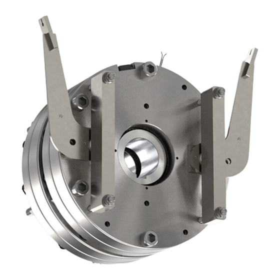
Product description 3.2.1 Basic module Fig. 1: Design of a BFK455-25 spring-applied brake Tappet Armature plate Complete rotor Flange Gear teeth Compression springs Coil Function This brake is an electrically releasable spring-applied brake with two rotating brake discs (rotors) that are equipped on both sides with friction linings. -
Page 13: Braking And Release
This design not only prevents the penetration of spray water and dust, but also the spreading of abrasion particles outside the brake. This is achieved by the following enclosures: ¾ A cover ring over the armature plate and rotor. INTORQ | BA 14.0215 | 07/2019... -
Page 14: Technical Specifications
Technical specifications Technical specifications Possible applications of the INTORQ spring-applied brake ¾ Degree of protection: – The brake is designed for operation under the environmental conditions that apply to IP54 protec- tion. Because of the numerous possibilities of using the brake, it is still necessary to check the func- tionality of all mechanical components under the corresponding operating conditions. - Page 15 The screws for the different brake attachment variants have different strength grades and may have special surface coatings. In order to guarantee a secure screw connec- tion, use ONLY the proper screws from INTORQ! ¾ It is very important to comply with the minimum thread depth of the end shield (refer to Rated data: screw kit for brake assembly onto flange, Page 15).
-
Page 16: Switching Times
Venting times under unfavorable conditions (240 switching operations per hour, 60% DC, 40 °C ambient temperature) Brake supplied with overexcitation (release voltage / holding voltage = 2 / 1) Max. speed according to type examination certificate (for higher speeds, please first contact the manufacturer) INTORQ | BA 14.0215 | 07/2019... - Page 17 Spark suppressors are available for the rated voltages. Disengagement time The disengagement time is the same for DC-side and AC-side switching. The specified disengagement times always refer to control using INTORQ rectifiers and rated voltage. INTORQ | BA 14.0215 | 07/2019...
-
Page 18: Friction Work / Operating Frequency
, the permissible amount of heat is Q Smax Notice With high speeds of rotation and switching energy, the wear increases strongly, because very high temperatures occur at the friction surfaces for a short time. INTORQ | BA 14.0215 | 07/2019... -
Page 19: Electromagnetic Compatibility
The user must ensure compliance with EMC Directive 2014/30/EC using appropriate controls and switching devices. NOTICE If an INTORQ rectifier is used for the DC switching of the spring-applied brake and if the operating frequency exceeds five switching operations per minute, the use of a mains filter is required. -
Page 20: Labels On Product
Type (refer to Product key, Page 3 ) 205/205 V DC Rated voltages of both braking circuits 425/425 W Rated powers for both braking circuits No. 33006670 ID number 1500/1500 NM Rated torque 26.04.18 Date of manufacture CE mark INTORQ | BA 14.0215 | 07/2019... - Page 21 Technical specifications Fig. 7: Product traceability sticker BFK455-25 Type (refer to Product key, Page 3 ) 33006670 ID number G1804260000000000 Serial number QR code INTORQ | BA 14.0215 | 07/2019...
-
Page 22: Mechanical Installation
The diameter of the shaft shoulder must not be greater than the tooth root diameter of the hub. ¾ The form and position tolerances apply only to the materials mentioned. Consult with INTORQ before using other materials; INTORQ's written confirmation is required for such usage. -
Page 23: Tools
Caliper gauge Feeler gauge Preparing the installation 1. Remove the packaging from the spring-applied brake and dispose of it properly. 2. Check the delivery for completeness. 3. Check the name plate specifications (especially rated voltage)! INTORQ | BA 14.0215 | 07/2019... -
Page 24: Installing The Hub Onto The Shaft
The customer is responsible for dimensioning the shaft-hub connection. Make sure that the supporting length of the key is identical to the length of the hub. NOTICE If you are using the spring-applied brake for reverse operations, glue the hub to the shaft. INTORQ | BA 14.0215 | 07/2019... -
Page 25: Brake Mounting
Only in the case of rotors with mounting paste on their gear teeth: ¾ Remove cover films from both front ends of the rotor. ¾ Protect friction surfaces against contact with mounting paste! ¾ After the mounting, excessive mounting paste must be removed properly! INTORQ | BA 14.0215 | 07/2019... - Page 26 1. Push the rotor onto the shaft and check that it can be moved by hand. Fig. 10: Mounting the first stator Complete stator Toothed shaft Rotor Flange End shield 2. Push the complete stator onto the shaft. INTORQ | BA 14.0215 | 07/2019...
- Page 27 4. Push the complete rotor onto the shaft and check that it can be moved by hand. Notice If a hand-release mechanism is to be installed, the required steps (in the Chapter Mounting the hand-release (retrofitting), Page 31 must be carried out now! INTORQ | BA 14.0215 | 07/2019...
- Page 28 7. Evenly tighten the brake with the six socket head cap screws included in the scope of supply in sev- eral runs using a torque wrench. 8. Establish the electrical connection and energize the brake (siehe Chapter Electrical connec- tion, Page 38). INTORQ | BA 14.0215 | 07/2019...
- Page 29 10. Switch off the power. Checking the air gap DANGER Danger: rotating parts! Switch off the voltage. The brake must be free of residual torque. s LN s LN Fig. 14: Checking the air gap INTORQ | BA 14.0215 | 07/2019...
-
Page 30: Cover Ring Assembly
5. Press the lips of the second cover ring into the groove of the first and second complete stators. 6. Re-establish the electrical connection. NOTICE Cover ring with condensation drain hole: Attach the cover ring so that condensation can drain through the bore hole. INTORQ | BA 14.0215 | 07/2019... -
Page 31: Mounting The Hand-Release (Retrofitting)
Components of the hand-release Hand-release lever Clip Self-locking nut Tension rod Pressure spring Self-locking nut 1. Mount the first rotor, the first complete stator, and the second rotor according to Chapter Brake mount- ing, Page 25. INTORQ | BA 14.0215 | 07/2019... - Page 32 (using a suitable tool). Notice The plates are not symmetric. The pin with the greater distance from the axis of rotation must be oriented towards the outside. The lever must also face outwards. INTORQ | BA 14.0215 | 07/2019...
- Page 33 4. From the armature plate end, plug one pair of pre-assembled tension rods each into the provided bore holes (Ø 9 mm) of the second stator. Insert the springs of the tension rod into the clearing hole of the armature plate (Ø 13.5 mm). INTORQ | BA 14.0215 | 07/2019...
- Page 34 6. Position the second stator in front of the first complete stator. Insert the pre-assembled tension rods into the through holes (Ø 9 mm) of the first complete stator. NOTICE Make sure that the tension rods are not bent! INTORQ | BA 14.0215 | 07/2019...
- Page 35 9. Establish the electrical connection and energize the brake (siehe Chapter Electrical installa- tion, Page 37). 10. Use a torque wrench to re-tighten the supplied fastening screws with the required tightening torque (Rated data: screw kit for brake assembly onto flange, Page 15). 11. Switch off the power. INTORQ | BA 14.0215 | 07/2019...
- Page 36 Rated data, Page 14 ), as shown in the Fig- ure Checking the air gap, Page 29. 13. Connect the Bowden cable (not included in this delivery) and pull until the motor shaft can be freely rotated. INTORQ | BA 14.0215 | 07/2019...
-
Page 37: Electrical Installation
K1/K3. ¾ The protective circuitry contained in the INTORQ switching device BEG-561-xxx is not permitted for use in the lift system. The protective circuitry must be connected in paral- lel to the brake coil (refer to the figure Switching suggestions for the BFK455-25, Page 38). -
Page 38: Electrical Connection
Protective Protective circuitry circuitry Brake Brake Fig. 22: Switching suggestions for the BFK455-25 Switching on ¾ K2/K4 must be switched on before or at the same time as K1/K3! Switching off ¾ Normal - AC switching – K2/K4 remain closed –... -
Page 39: Bridge/Half-Wave Rectifier (Optional)
The bridge-half-wave rectifiers are used to supply electromagnetic DC spring-applied brakes which are ap- proved for use with such rectifiers. Other use is only permitted with the approval of INTORQ. Once a set overexcitation period has elapsed, the bridge-half-wave rectifiers switch over from bridge recti- fication to half-wave rectification. -
Page 40: Technical Specifications
1.300 1.200 Tab. 6: Data for bridge/half-wave rectifier type BEG-561 6.2.3 Permissible current load at ambient temperature Fig. 24: Permissible current load If screwed to metal surface (good heat dissipation) For other installations (e.g. with adhesive) INTORQ | BA 14.0215 | 07/2019... -
Page 41: Commissioning And Operation
8. It must be zero and the rotor must rotate freely. 9. Check the switching status of the micro-switch (siehe to table Switching status of micro- switch, Page 42). 10. Open the switching contact for the brake. – The brake is applied. INTORQ | BA 14.0215 | 07/2019... -
Page 42: Commissioning
Bridge/half-wave rectifier – brake size, Page 39). A deviation of ±10 % is permissible. ¾ If a fault occurs once, go through the troubleshooting table (siehe the chapter Troubleshooting and fault elimination, Page 48). If the fault cannot be fixed or eliminated, please contact the customer ser- vice department. INTORQ | BA 14.0215 | 07/2019... -
Page 43: Maintenance And Repair
Maintenance and repair Maintenance and repair INTORQ spring-applied brakes are wear-resistant and designed for long maintenance intervals. The friction lining and braking mechanism are subject to operational wear. To ensure safe and trouble-free operations, the brake must be checked at regular intervals and replaced when necessary (refer to the table Maintenance intervals, Page 44). -
Page 44: Inspections
After replacing the rotor, the original braking torque will not be reached until the run-in op- eration for the friction surfaces has been completed. After replacing the rotor, the run-in armature plates and the flanges have an increased initial rate of wear. INTORQ | BA 14.0215 | 07/2019... -
Page 45: Release / Voltage
" near the fastening screws between the armature plate and the stator using a feeler gauge. 3. Compare the measured air gap to the max. permissible air gap "s ". (Refer to the table Rated Lmax data, Page 14 for the values.) 4. When necessary, replace both rotors completely. INTORQ | BA 14.0215 | 07/2019... -
Page 46: Checking The Rotor Thickness
7. Check the end shield's friction surface. Replace the friction surface on the end shield when there is clearly visible scoring at the running surface. In case of strong scoring on the end shield, rework the friction surface. 8. Mount the new rotor and the stator. 9. Re-connect the connection cables. INTORQ | BA 14.0215 | 07/2019... -
Page 47: Spare Parts List
Spring-applied brake 455-25 Designation Variant ¾ for mounting to the flange with through-holes Fastening screws Socket head cap screw set, DIN912 ¾ for mounting to the motor Complete stator Voltage Complete rotor Cover ring Flange INTORQ | BA 14.0215 | 07/2019... -
Page 48: Troubleshooting And Fault Elimination
¾ If the rectifier defect occurs again, replace the entire spring-applied brake, even if you cannot find any fault between turns or short circuit to ground. The error may only occur on warming up. INTORQ | BA 14.0215 | 07/2019... - Page 49 Incorrect micro-switch wir- AC voltage is not mains Check and correct the wiring of the micro-switch. voltage Micro-switch defective or in- Replace the complete stator and return the defective correctly set complete stator to the manufacturer. INTORQ | BA 14.0215 | 07/2019...
- Page 50 INTORQ GmbH & Co KG Germany PO Box 1103 D-31849 Aerzen, Germany Wülmser Weg 5 D-31855 Aerzen, Germany +49 5154 70534-0 (Headquarters) +49 5154 70534-222 (Sales) Ê +49 5154 70534-200 š info@intorq.com 应拓柯制动器(上海)有限责任公司 INTORQ (Shanghai) Co., Ltd. 上海市浦东新区泥城镇新元南路600 号6 号楼一楼B 座...
Need help?
Do you have a question about the BFK455-25 and is the answer not in the manual?
Questions and answers