
Related Manuals for INTORQ BFK457 Series


Summary of Contents for INTORQ BFK457 Series
- Page 1 BA 14.0164 13053267 EN Operating Instructions Spring-applied brakes with electromagnetic release INTORQ BFK457-...
- Page 2 Product group Brakes Product family Spring-applied brakes Type Size • The data indicated in the product key and on the nameplate and stickers on the packaging are valid for spring-applied brakes of the series INTORQ BFK457. Nameplate Assembly Field Contents Example...
- Page 3 E 2005 INTORQ GmbH & Co. KG No part of this documentation may be reproduced or made accessible to third parties without written consent by INTORQ GmbH & Co. KG. All indications given in these Operating instructions have been selected carefully. We will include necessary corrections in subsequent editions.
-
Page 4: Table Of Contents
......... . . 4.3.2 Installation of the brake INTORQ BFK457-01...16, compact design ..... . - Page 5 6.2.1 Inspection of brake INTORQ BFK457-01...16 ........
-
Page 6: Preface And General Information
• After reception of the delivery, check immediately whether the scope of supply matches with the accompanying papers. INTORQ GmbH & Co. KG does not accept any liability for deficiencies claimed subsequently. Claim – visible transport damage immediately to the forwarder. -
Page 7: Drive Systems
– operating mistakes – disregarding these Instructions. Warranty • Warranty conditions: see Sales and Delivery Conditions of INTORQ GmbH & Co. KG. • Warranty claims must be made to the INTORQ representative responsible for you immediately after detecting defects or faults. -
Page 8: Safety Information
The spring-applied brake must only be operated in perfect state. • Retrofittings or changes of the spring-applied brake are generally prohibited. In any case, INTORQ GmbH & Co. KG must be contacted. • The friction linings must be carefully protected from grease or oil since even small amounts of lubricants reduce the brake torque considerably. -
Page 9: Layout Of The Safety Information
Safety information Possible applications of the spring-applied brake INTORQ BFK457- • No explosive or agressive atmostphere. • Humidity, no restriction. • Ambient temperature -20_C bis +40_C. • With high humidity and low temperatures – Take measures to protect armature plate and rotor from freezing. -
Page 10: Technical Data
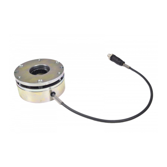
Armature plate Spring Spacer Rotor with friction lining Flange Socket kead screws DIN912 Fig. 1 Spring-applied brake: INTORQ BFK457-01...16 Compact, completely mounted with rotor and flange Sticker - nameplate Stator Armature plate Spring Spacer Rotor with friction lining Elastic band (shipping bracket) Socket head screws DIN912 Lü... -
Page 11: General
Please take into account that the friction value and thus the torque depend on the speed. Stop! The spring-applied brakes INTORQ BFK457, sizes 01 to 16 use spacers (1.6). It is not possible to readjust the brake in the event of wear. If necessary, the rotor must be replaced. -
Page 12: Rated Data
INTORQ BFK457-12 INTORQ BFK457-14 3 x M8 3 x M8 INTORQ BFK457-16 Minimum brake torque when all components are run in. Minimum air gap, effective value results from the sum tolerances of the single components. BA INTORQ BFK457 EN 2.0... - Page 13 Technical Data BA INTORQ BFK457 EN 2.0...
-
Page 14: Switching Times
5 to 10 times rated voltage. The diagramme shows the delay during engagement t , the rise time of the brake torque t and the engagement time t ,as well as the disengagement time t BA INTORQ BFK457 EN 2.0... -
Page 15: Operating Frequency / Friction Work
S results in the permissible friction work Q perm With high speed and friction work, the wear increases strongly, because very high temperatures occur at the friciton faces for a short time. BA INTORQ BFK457 EN 2.0... -
Page 16: Emission
Depending on the natural oscillation after installation, operating conditions and state of the friction faces, the brake may squeak during braking. Others The abrasion of the friction parts produces dust. With large loards, the frction face heats up so strongly, that odours may occur. BA INTORQ BFK457 EN 2.0... -
Page 17: Installation
3 - 40 5x1/2” square 180mm long 5x1/2” square 180mm long INTORQ BFK457-12 INTORQ BFK457-14 20 100 20 - 100 6x1/2” square 140mm long 6x1/2” square 140mm long INTORQ BFK457-16 Feeler gauge Caliper gauge Multimeter BA INTORQ BFK457 EN 2.0... -
Page 18: Assembly
Square hubs must be used for the sizes 01 and 02! Circlip 10.0 10.0 Endshield K14.0611 Fig. 5 Installation of the hub onto the shaft 1. Press hub (3.0) onto the shaft. 2. Secure hub against axial displacement (e.g. using a circlip - 3.1). BA INTORQ BFK457 EN 2.0... -
Page 19: Installation Of The Brake Intorq Bfk457-01
Installation 4.3.2 Installation of the brake INTORQ BFK457-01...16, compact design 1. Hub (3.0) installation, chapter 4.3.1. 2. Push spring-applied brake (1.0) onto the hub (3.0). Secure hub against axial displacement (e.g. using a circlip - 3.1). 3. Bolt the spring-applied brake (1.0) to the endshield using the fixing screws (8.1). -
Page 20: Installation Of The Brake Intorq Bfk457-06
Installation 4.3.3 Installation of the brake INTORQ BFK457-06...16, basic design 1. Mount the hub (3.0), chapter 4.3.1 2. Push the spring-applied brake onto the hub (3.0), secure the hub against axial displacement with a circlip (3.1). 3. Tighten the brake fixing screws lightly and remove the shipping brace (elastic band). -
Page 21: Electrical Connection
Installation U = X D.C. ±10% Electrical connection Warning! The brake must only be electrically connected when no voltage is applied. ➀ Bridge rectifier ➀ K14.0525 Fig. 6 Switching parallel to motor, extremely delayed engagement BA INTORQ BFK457 EN 2.0... - Page 22 Bridge rectifier ➀ K14.0525/7 Fig. 8 DC switching, normal engagement ➀ ➀ DC voltage (e. g. 24V) ➁ Spark suppressor Connection diagram also valid for star connection ➁ K14.0525/3 Fig. 9 Separated DC voltage, DC switching. BA INTORQ BFK457 EN 2.0...
-
Page 23: Commissioning And Operation
– loose fixing elements – the state of the cables. • In the event of failures, refer to the trouble shooting table in chapter 7. If the fault cannot be eliminated, please contact the INTORQ representative. BA INTORQ BFK457 EN 2.0... -
Page 24: Maintenance / Repair
Inspections 6.2.1 Inspection of brake INTORQ BFK457-01...16 6.2.1.1 Air gap Warning! The motor must be at standstill when checking the air gap. -
Page 25: Maintenance
The order numbers are only valid for standard versions. • Bore diameter in mm • Standard keyway to DIN 6885/1 P9 BFK457-012-2 Fig. 10 Spare parts for spring-applied brakes INTORQ BFK Size 01...16 Pos. Name Variant Spring-applied brake Size Voltage... -
Page 26: Order Of Spare Parts
Maintenance Order of spare parts Receiver: INTORQ GmbH & Co. KG 31849 Aerzen Fax no.: +49 51 54 / 95 39-10 Spring-applied brake INTORQ BFK457- Sender Company ________________________________________ Customer no. ________________________ Street/P .O.box ________________________________________ Order no. ________________________ Postal code / City ________________________________________... -
Page 27: Troubleshooting And Fault Elimination
Adapt rectifier and brake voltage to each other. Defective rectifier diode Replace rectifier by a suitable new one. AC voltage is not mains voltage Fuse missing or defective Select connection where fuse has not been removed and is o.k. BA INTORQ BFK457 EN 2.0... - Page 28 Notes BA INTORQ BFK457 EN 2.0...
Need help?
Do you have a question about the BFK457 Series and is the answer not in the manual?
Questions and answers