Advertisement
Quick Links
A A
R R E E A A D D A A N N D D S S A A V V E E T T H H E E S S E E I I N N S S T T R R U U C C T T I I O O N N S S F F O O R R F F U U T T U U R R E E R R E E F F E E R R E E N N C C E E
R R E E A A D D A A N N D D S S A A V V E E T T H H E E S S E E I I N N S S T T R R U U C C T T I I O O N N S S F F O O R R F F U U T T U U R R E E R R E E F F E E R R E E N N C C E E
B B E E F F O O R R E E I I N N S S T T A A L L L L A A T T I I O O N N
W W A A R R N N I I N N G G ! !
T T O O R R E E D D U U C C E E T T H H E E R R I I S S K K O O F F F F I I R R E E , , E E L L E E C C T T R R I I C C A A L L S S H H O O C C K K , , O O R R
I I N N J J U U R R Y Y T T O O P P E E R R S S O O N N S S , , O O B B S S E E R R V V E E T T H H E E F F O O L L L L O O W W I I N N G G : :
1.
Use this unit in the manner intended by the manufacturer.
If you have any questions, contact the manufacturer.
2.
Before servicing or cleaning unit, switch power off at service
panel and lock the service disconnecting means to prevent
power from being switched on accidentally. When the service
disconnecting means cannot be locked, securely fasten a
prominent warning device, such as a tag, to the service panel.
3.
Installation work including the electrical wiring must
be done, in accordance with all applicable codes and
standards, by a qualified person.
4.
When cutting into ceilings, take care not to damage
concealed electrical wiring or any other hidden utilities.
5.
Ducted fans must always be vented to the outdoors.
6.
NEVER place a switch where it
can be reached from a tub or
shower. To prevent electrical
hazards the fan must be
installed so as to prevent water
from entering the fan. The fan
must not be installed in a place
that is prone to water leakage.
7.
Not for use in cooking areas.
(Figure 1)
8.
These fans must be mounted to structural members that are
strong enough to support the fan's weight.
9.
The fan must be properly grounded.
10. Do not allow foreign objects to enter the fan; this could
result in electric shock or fan damage.
11. Do not block the air intake or exhaust.
12. The fan should not be turned on and off rapidly.
13. If the fan is not operating properly, shut the power off
immediately, and have a certified electrician inspect it and
have it serviced as required.
14. Do not clean the fan with corrosive chemicals nor water in
excess of 60C (140F).
15. Power supply wiring is to be No. 14AWG wire or larger
(suitable for at least 90C (190F)).
16. Not for use outdoors.
17. For the lighted units, use only PL type 26W lamps and
a maximum of 4W type E12 T20 lamp for the night light
(models TBFR90L, TBFS90L, TBFR120L, TBFS120L).
18. The fan is type IC (Inherently Protected).
19. The fan must not be installed in a ceiling with an "R" rating
greater than 40.20.
To reduce the risk of injury, install
the fan at least 2.1m (7 feet) above the floor.
21. The following models are suitable for installation over a
shower or tub when installed in a GFCI protected branch
circuit (TBF90, TBF120, TBFR90L and TBFR120L).
22. W W A A R R N N I I N N G G : : To reduce the risk of fire or electrical shock, do
not use this fan with any solid state speed control device.
F F
S S
E E R R O O
A A N N
U U P P E E R R I I O O R R
P P A A C C K K A A G G E E C C O O N N T T E E N N T T S S
•
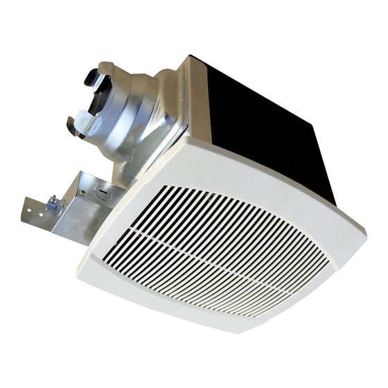
A A e e r r o o F F a a n n superior bathroom fan
• Mounting brackets (3)
• Lamps - 26W PL & 4W night light (selected models only)
Cooking area
Do not install above
or inside this area
o
o
45
45
Cooking
Floor
Equipment
Figure 1
I I N N S S T T A A L L L L A A T T I I O O N N & & M M A A I I N N T T E E N N A A N N C C E E
B B
A A T T H H R R O O O O M M
C C A A U U T T I I O O N N ! !
1.
For general ventilating use only. Do not use to exhaust
hazardous or explosive materials and vapors.
2.
This product is designed for installation in flat ceilings
only. Do not install it in a sloping ceiling or in a wall.
3.
To avoid motor bearing damage and noisy unbalanced
impellers keep construction material / dust from entering
the fan.
4.
Please read specification label on the product for further
information and requirements.
F F A A N N I I N N S S T T A A L L L L A A T T I I O O N N
The fan should only be installed in a ceiling (see figure 2 for a
typical installation). The fan will accommodate a joist spacing
of 16" with a minimum clearance height of 9".
Power
Ceiling
Figure 2
1.
Remove the grille by
gently squeezing the wire
springs and extracting
them from the slots in
the housing.
2.
Remove the electrical
box cover and install
the 3 brackets on the
fan housing. (Figure 3)
3.
To install the housing in
the ceiling, position it
between the joists and
extend the brackets to the
adjacent joists. Mark the
screw locations (at the top
of the keyhole on each
bracket) on the joists.
Note: make sure to allow
the appropriate depth for
the particular ceiling type.
The bottom edge of the
housing should be flush
with the ceiling. (Figure 4)
4.
Remove the housing and
drive the screws part way
into the joists at the
marked locations.
I I N N S S T T R R U U C C T T I I O O N N S S
F F
A A N N S S
Housing
Fan Outlet
Ceiling Joist
Grille
Mounting
Electrical
Electrical
Bracket
Box
Box Cover
Figure 3
Figure 4
Ceiling
Advertisement

Related Manuals for CFM TBF90


Summary of Contents for CFM TBF90
- Page 1 Figure 4 drive the screws part way circuit (TBF90, TBF120, TBFR90L and TBFR120L). into the joists at the 22. W W A A R R N N I I N N G G : : To reduce the risk of fire or electrical shock, do not use this fan with any solid state speed control device.
- Page 2 W W I I R R I I N N G G P P R R O O C C E E D D U U R R E E TBFR90L TBFR120L Refer to the wiring diagrams below. FAN ONLY (MODELS TBF90, TBF120) EXHAUST FAN SWITCH BY OTHERS MODEL TBF90 & TBF120...